Pulse Auxiliary Source
The pulse input source can be used to pulse a voltage between two or three voltages. The source includes probes for both the source voltage and current.
In this topic:
| Model Name | Pulse Auxiliary Source | |
| Simulator |
|
This device is compatible with both the SIMetrix and SIMPLIS simulators. |
| Parts Selector Menu Location |
||
| Symbol Library | None - the symbol is automatically generated when placed or edited. | |
| Model File | SIMPLIS_DVM_ADVANCED.lb | |
| Subcircuit Name | SIMPLIS_DVM_ADVANCED_SOURCE_AUX_PULSE | |
| Symbols |  |
|
| Schematic |
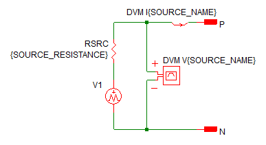
|
|
Pulse Auxiliary Source Parameters
The following table explains the relevant parameters.
| Parameter Name | Default | Data Type | Range | Units | Parameter Description |
| FALL_TIME | 50u | Real | min: 0 | s | The fall time of the source |
| FINAL_VOLTAGE | 12 | Real | V | The final voltage of the source | |
| PULSE_VOLTAGE | 9 | Real | V | The pulse voltage of the source | |
| PULSE_WIDTH | 200u | Real | min: 0 | s | The time which the source voltage is the PULSE_VOLTAGE |
| RISE_TIME | 100u | Real | min: 0 | s | The pulse rise time in seconds |
| SOURCE_NAME | SRC | String | n/a | n/a | Name of the DVM source. This name cannot contain spaces. |
| SOURCE_RESISTANCE | 0.4 | Real | min:0 | Ω | Sets the source resistance of the source |
| START_VOLTAGE | 5 | Real | V | The starting voltage for the source | |
| TIME_DELAY | 10u | Real | min: 0 | s | The time delay before the pulse initiates |
Testplan Entry for the Pulse Auxiliary Source
To set any DVM Aux source to a Pulse Auxiliary Source subcircuit, place a Pulse testplan entry in the Source column.
The Pulse() testplan entry has the following syntax with the arguments explained in the table below.
Pulse(REF, START_VOLTAGE, PULSE_VOLTAGE, FINAL_VOLTAGE)
Pulse(REF, START_VOLTAGE, PULSE_VOLTAGE, FINAL_VOLTAGE, OPTIONAL_PARAMETER_STRING)
where:
| Argument | Range | Description |
| REF | n/a | The actual reference designator of the DVM AUX source. |
| START_VOLTAGE | min: 0 | The starting voltage for the source. |
| PULSE_VOLTAGE | min: 0 | The pulse voltage for the source. |
| FINAL_VOLTAGE | min: 0 | The final voltage for the source. |
| OPTIONAL_PARAMETER_STRING | n/a |
Parameter string with a combination of one or more timing parameters:
|
* If more than one parameter is specified, join the parameter key-value pairs with a space, as shown in the example below. The order of the parameter names does not matter.
Timing
The timing for the Pulse Source is determined by the following parameters.
- TIME_DELAY
- RISE_TIME
- PULSE_WIDTH
- FALL_TIME
Timing parameters can be assigned using the optional parameter string as shown in the following examples.
Symmetric Pulse Example
This example shows a symmetric pulse with equal rise and fall times. The final voltage is the same as the starting voltage.
| *?@ Source |
|---|
| Pulse(V5, 1, 5, 1, TIME_DELAY=25u RISE_TIME=25u PULSE_WIDTH=100u FALL_TIME=25u) |
The results of this testplan entry are shown below:
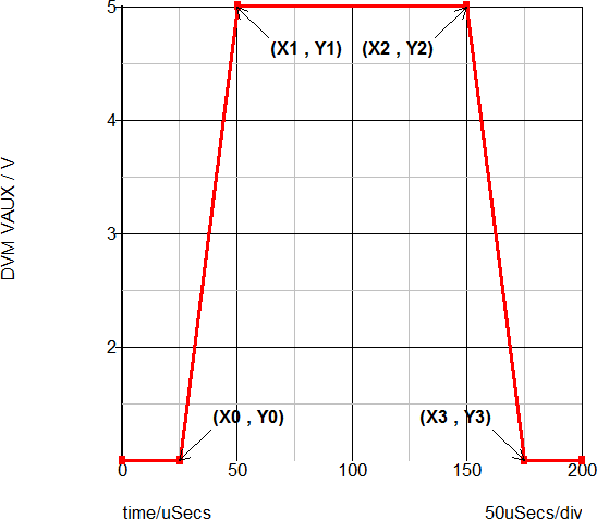
| Annotation | Value |
| X0 | TIME_DELAY |
| X1 | TIME_DELAY + RISE_TIME |
| X2 | TIME_DELAY + RISE_TIME + PULSE_WIDTH |
| X3 | TIME_DELAY + RISE_TIME + PULSE_WIDTH + FALL_TIME |
| Y0 | START_VOLTAGE |
| Y1 | PULSE_VOLTAGE |
| Y2 | PULSE_VOLTAGE |
| Y3 | FINAL_VOLTAGE |
Asymmetric Pulse Example
The following example sets the DVM Aux Source with reference designator V5 to a Pulse Aux Voltage Source, with a starting voltage of 1V, a pulse voltage of 5V and a final voltage of 4.5V. Note the rise and fall times are not the same and the pulse does not have to return to the starting voltage value.
| *?@ Source |
|---|
| Pulse(V5, 1, 5, 4.5, TIME_DELAY=25u RISE_TIME=25u PULSE_WIDTH=75u FALL_TIME=50u) |
The results of this testplan entry are shown below:
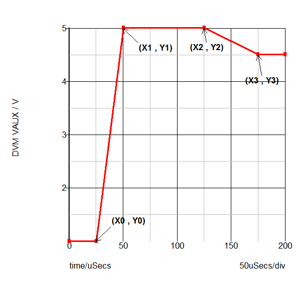
| Annotation | Value |
| X0 | TIME_DELAY |
| X1 | TIME_DELAY + RISE_TIME |
| X2 | TIME_DELAY + RISE_TIME + PULSE_WIDTH |
| X3 | TIME_DELAY + RISE_TIME + PULSE_WIDTH + FALL_TIME |
| Y0 | START_VOLTAGE |
| Y1 | PULSE_VOLTAGE |
| Y2 | PULSE_VOLTAGE |
| Y3 | FINAL_VOLTAGE |