Non-Linear 4-Quadrant (NLB) Multipliers
The SIMPLIS 4-Quadrant Nonlinear Block (NLB) components are primitive components in SIMPLIS which support the modeling of PFC controllers. The 4-Quadrant versions were introduced with version 8.30, and will require 8.30 or a newer version of SIMPLIS. These NLB components are not intended for general-purpose nonlinear modeling. For alternative multipliers, see the PWM Multipliers and PWL Multipliers topics. For single quadrant versions of the NLB Multipliers, see Non-Linear Block (NLB) Multiplier/Dividers.
The modeling and the equations used in the NLB components are not compatible with the POP analysis. Hence the POP analysis and the AC analysis, which depends on the successful conclusion of the POP analysis, are both disabled when NLB components are present. Both the PWM Multipliers and PWL Multipliers are compatible with the POP and AC analyses.
In this topic:
| Model Name: | 4- Quadrant Non-Linear Multiplier | |
| Simulator: | 
|
This device is compatible with the SIMPLIS simulator |
| Parts Selector Menu Location: |
|
|
| Symbol Library: | SIMPLIS_NLB.sxslb | |
| Model File: | SIMPLIS_NLB.lb | |
| Symbol Names: |
|
|
| Subcircuit Names: |
|
|
| Example Symbol: | 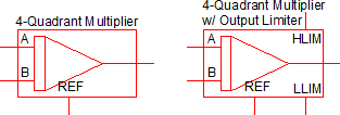
|
|
| Multiple Selections: | Only one POP Trigger device is permitted on a schematic. | |
Editing the 4-Quadrant NLB Multiplier
To configure the NLB Multiplier, follow these steps:
- Double click the symbol on the schematic to open the editing dialog.
- Make the appropriate changes to the fields described in the table below the image.
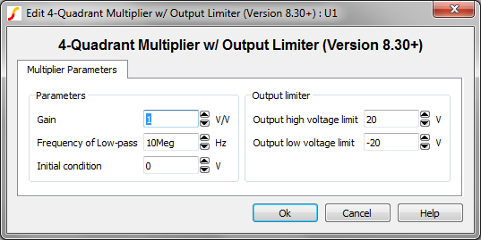
| Parameter Label | Units | Description |
| Gain | The gain of the multiplier in V/V. | |
| Frequency of Low-pass | Hz | The low pass cutoff frequency of the internal filter for each input in Hz. |
| Initial condition | V | The initial condition of the output in volts. |
| Output high voltage limit | V | The maximum voltage allowed at the output pin. The output is limited to voltages less than this parameter value or the instantaneous voltage on the HLIM pin, which ever is less. |
| Output low voltage limit | V | The minimum voltage allowed at the output pin. The output is limited to voltages greater than this parameter value or the voltage on the LLIM pin, whichever is greater. |
Model Details
Each non linear block multiplier/divider have the following attributes:
- Each component has a reference pin, named REF. In most applications, this pin is tied to ground. All input voltages and the multiplier/divider output are defined with respect to this pin.
- There is a resistive input impedance of 10 GΩ between each input pin and the reference pin and there is a resistive output impedance of 50 ohms between the output pin and the reference pin.
- All input signals are defined as the differential voltages of the input pins with respect to the reference pin. The output signal is defined as the differential voltage of the output pin with respect to the reference pin.
- For the "w/ Output Limiter" version, the maximum value of the output is limited to
the lower of the following two values:
- The differential voltage of the HLIM pin with respect to the reference pin.
- The value set to the “Output High Voltage Limit” in the GUI dialog.
- The Gain is applied at the output - effectively gaining the mathematical product of the block.
- There is a low-pass filter placed in the output stage of each NLB component. Hence, instantaneous jumps in the input signals will not cause an instantaneous jump in the output voltage.
4-Quadrant Multiplier Example
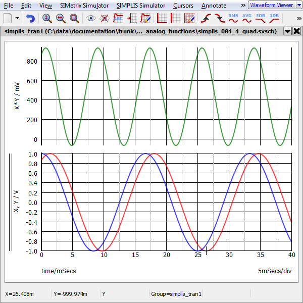
A basic four quadrant multiplier example schematic can be downloaded here: simplis_084_4_quad.sxsch. In this example, the amplitude and phase between the two sine wave sources is defined in the F11 window with a variable statement. The product of the two sine wave sources is output from the 4-quadrant multipler.
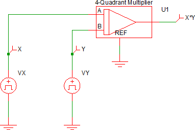
The simulation results from this circuit are:
4-Quadrant Multiplier w/ Limiter Example
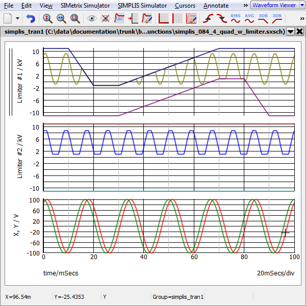
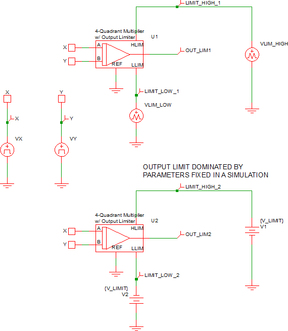
A four quadrant multiplier with limiter example schematic can be downloaded here: simplis_084_4_quad_w_limiter.sxsch. In this example, the amplitude and phase between the two sinusoidal waveform sources is defined in the F11 window with a variable statement. Two multipliers are used to multiply the sinusoidal waveforms - the upper multiplier (U1) output is dominated by the two external sources, VLIM_HIGH and VLIM_LOW. The output of the lower multiplier (U2) is only dependent on the parameter values entered into the multiplier's editing dialog.
The simulation results from this circuit are:
