Example 1 -- Rectifier with RC load
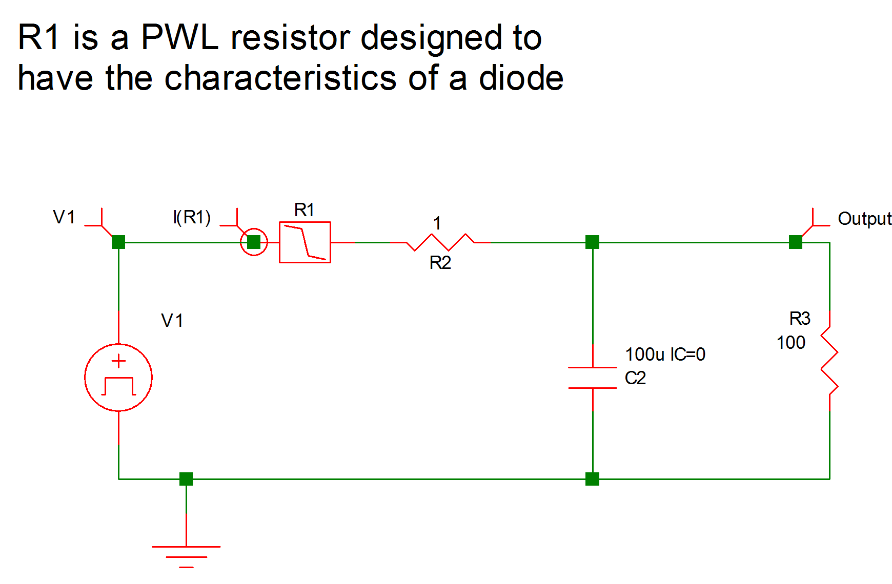
The system under study in this example is the simple rectifier circuit shown in Figure 9.1. The ac voltage source V1 is a 154-V peak-to-peak 60 Hz sinusoidal voltage source. The variables of interest are the voltage across the ac voltage source, the voltage across the filter capacitor, and the current through the diode, which is modeled by the piecewise-linear resistor R1 (!R$R1 in the input file). The input file for the circuit of Example 1 is shown in Figure 9.2.
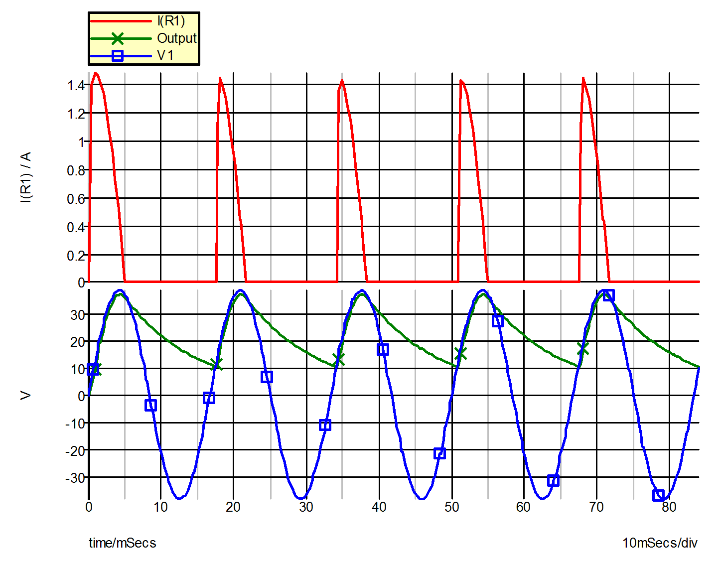
The time-domain simulation is carried out for 84 milliseconds, which is slightly longer than five complete cycles of the 60 Hz ac source. The parameter PSP_NPT is set to 211, instructing SIMPLIS to create the Time-Domain Print/Plot File with the print variables V(V1), V(C2), and I(R1) and a time resolution of [(84) / (211 _ 1)] = 0.4 msec.
Waveforms obtained from this simulation are shown in Figure 9.3.
 |
9.1 Example 1: Rectifier with RC Load |
* Single RC Source Rectified into a RC Low-Pass Filter
.PRINT  ALL
.OPTIONS  PSP_NPT=211
.TRAN 84m 0

V1 1 0 SIN VOFFSET=0 APEAK=38.5 FREQ=60 TDELAY=0
+ OFF_UNTIL_DELAY=NO DAMP_COEF=0
C2 3 0 100u IC=0
!R$R1 1 2 R1$TP_SSPWLR IC=1
.MODEL R1$TP_SSPWLR VPWLR NSEG=2 X0=0 Y0=0 X1=1 Y1=0.5U
+ X2=1.1 Y2=1
R2 3 2 1
R3 0 3 100

.END
 |
9.3 Waveforms for Example 1 |
| ◄ Overview | Example 2 -- 3-Phase Rectifier with Resistive Load ▶ |