Voltage Source
In this topic:
Netlist Entry
Vxxxx n+ n- [[DC] dcvalue] [DCOP] [INFCAP] [AC magnitude [phase]]
[transient_spec]
| N+ | Positive node |
| N- | Negative node |
| DCOP | If this is specified, the voltage source will only be active during the DC operating point solution. In other analyses, it will behave like an open circuit. This is an effective method of creating a 'hard' initial condition. See Alternative Initial Condition Implementations for an example. |
| INFCAP | If specified, the voltage source will behave as an infinite capacitor. During the DC operating point solution it will behave like an open circuit. In the subsequent analysis, it will behave like a voltage source with a value equal to the solution found during the operating point. Note that the device is inactive for DC sweeps - as all capacitors are. |
| dcvalue | Value of source for dc operating point analysis |
| magnitude | AC magnitude for AC sweep analysis. |
| phase | phase for AC sweep analysis |
| transient_spec | Specification for time varying source as described in the following table. |
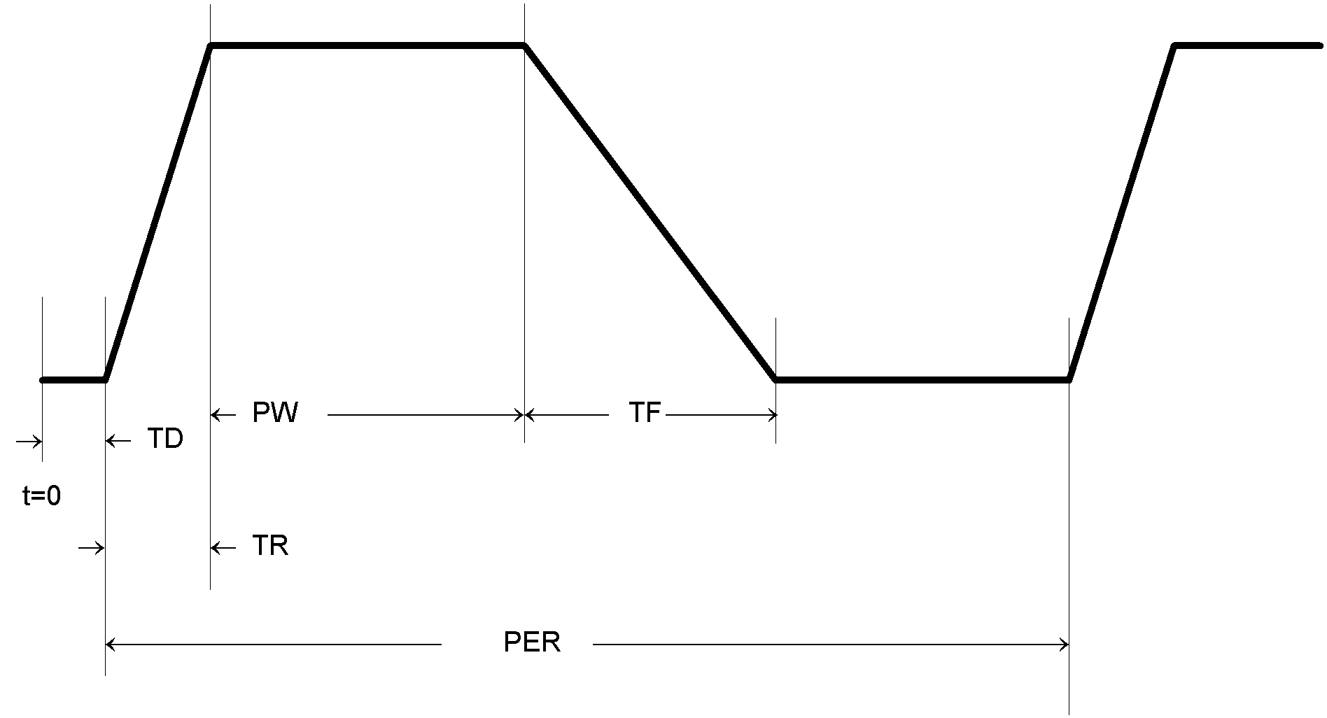
Pulse Source
PULSE ( v1 v2 [td [tr [tf [pw [per ]]]]] )
Where:
| Name | Description | Default |
| v1 | Initial value (V,A) | Compulsory |
| v2 | Pulsed value (V,A) | Compulsory |
| td | Delay time (S) | Default if omitted = 0 |
| tr | Rise time (S) | Default if omitted, negative or zero = Time stepa |
| tf | Fall time (S) | Default if omitted, negative or zero = Time step |
| pw | Pulse width (S) | Default if omitted or negative = Stop timeb |
| per | Period (S) | Default if omitted, negative or zero = Stop time |
| a. | Time step is set up by the .TRAN simulator statement which defines a transient analysis. Refer to .TRAN. |
| b. | Stop time refers to the end time of the transient analysis. |
SIMetrix deviates from standard SPICE in the action taken for a pulse width of zero. Standard SPICE treats a zero pulse width as if it had been omitted and changes it to the stop time. In SIMetrix a zero pulse width means just that.
Both the above examples give a pulse lasting 5???MATH???\mu???MATH???S with a period of 10???MATH???\mu???MATH???S, rise and fall times of 100nS and a delay of 0. The voltage source has a 0V base line and a pulse of 5V while the current source has a 0mA base line and a pulse of 1mA.
Examples

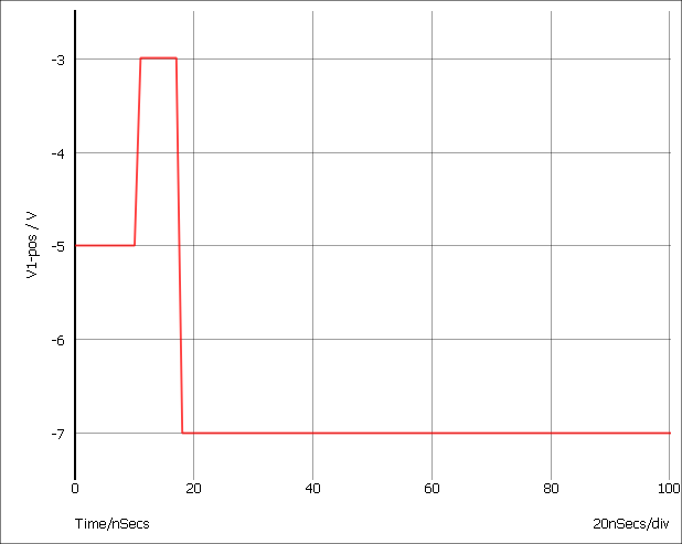
Piece-Wise Linear Source
PWL ( t1 v1 [t2 v2 [t3 v3 [... ]]] )
Each pair of values (ti vi) specifies that the value of the source is vi at time = ti. The value of the source at intermediate values of time is determined by using linear interpolation on the input values.
Although the example given below is for a voltage source, the PWL stimulus may be used for current sources as well.
Example

Gives:
PWL File Source
PWLFILE filename
This performs the same function as the normal piece wise linear source except that the values are read from a file named filename.
The file contains a list of time voltage pairs in text form separated by any whitespace character (space, tab, new line). It is not necessary to add the '+' continuation character for new lines but they will be ignored if they are included. Any non-numeric data contained in the file will also be ignored.
Notes
The PWLFILE source is considerably more efficient at reading large PWL definitions than the standard PWL source. Consequently it is recommended that all PWL definitions with more than 200 points are defined in this way.
The data output by Show /file is directly compatible with the PWLFILE source making it possible to save the output of one simulation and use it as a stimulus for another. It is recommended, however, that the results are first interpolated to evenly spaced points using the Interp() function.
The use of engineering suffixes (e.g. k, m, p etc.) is not supported by PWLFILE.
The PWLFILE source is a feature of SIMetrix and does not form part of standard SPICE.
Note, you can use the simulator statements .FILE and .ENDF to define the contents of the file. E.g.
Vpwl1 N1 N2 PWLFILE pwlSource
...
.FILE pwlSource
...
...
.ENDF
This will be read in much more efficiently than the standard PWL and is recommended for large definitions. See .FILE and .ENDF.
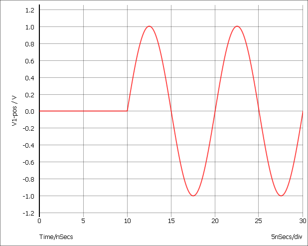
Sinusoidal Source
SIN[E] ( vo va [freq [delay [theta [ phase]]]] )
Where:
| Name | Description | Default |
| vo | Offset (V,A) | Compulsory |
| va | Peak (V,A) | Compulsory |
| freq | Frequency (Hz) | Default if omitted or zero= 1/Stop timea |
| delay | Delay (seconds) | Default if omitted = 0 |
| theta | Damping factor (1/seconds) | Default if omitted = 0 |
| phase | Phase in degrees | Default if omitted = 0 |
| a. Stop time refers to the end time of the transient analysis. |
The shape of the waveform is described by:
| 0 to delay: | vo |
| delay to Stop time | ???MATH???vo + va \cdot \text{e}^{-(t-\textit{delay})..\textit{theta}} \cdot \sin(2\pi(\textit{freq} \cdot (t - \textit{delay}) + \textit{phase}/360))???MATH??? |
Example

Gives output of:
Exponential Source
EXP ( v1 v2 [td1 [tau1 [td2 [tau2 ]]]] )
Where:
| Name | Description | Default |
| v1 | Initial value (V,A) | Compulsory |
| v2 | Pulsed value (V,A) | Compulsory |
| td1 | Rise delay time | Default if omitted or zero: 0 |
| tau1 | Rise time constant | Default if omitted or zero: Time stepa |
| td2 | Fall delay time | Default if omitted or zero: td1 + Time step |
| tau2 | Fall time constant | Default if omitted or zero: Time step |
| a. | Time step is set up by the .TRAN simulator directive which defines a transient analysis. Refer to .TRAN. |
| td1 to td2: | ???MATH???v1 + (v2 - v1). [ 1 - \text{e}^{-(t-td1)/tau1}]???MATH??? |
| td2 to stop time: | ???MATH???v1 + (v2 - v1). [ 1 - \text{e}^{-(t-td1)/tau1}] + v1 + (v2 - v1). [ 1 - \text{e}^{-(t-td2)/tau2}]???MATH??? |
Single Frequency FM
SFFM ( vo va [fc [mdi [fs ]]] )
Where:
| Name | Description | Default |
| vo | Offset (V,A) | Compulsory |
| va | Amplitude (V,A) | Compulsory |
| fc | Carrier frequency (Hz) | Default if omitted or zero = 1/Stop timea |
| mdi | Modulation index | Default if omitted = 0 |
| fs | Signal frequency (Hz) | Default if omitted or zero = 1/Stop time |
| a. | Stop time refers to the end time of the transient analysis. |
Defined by: ???MATH???vo + va\cdot\sin[2\pi\cdot \textit{fc}\cdot t + \textit{mdi}\cdot\sin(2\pi\cdot\textit{fs}\cdot t)]???MATH???
Noise Source
noise interval rms_value [start_time [stop_time]]
Source generates a random value at interval with distribution such that spectrum of signal generated is approximately flat up to frequency equal to 1/(2*interval). Amplitude of noise is rms_value volts. start_time and stop_time provide a means of specifying a time window over which the source is enabled. Outside this time window, the source will be zero. If stop_time is omitted or zero a value of infinity will be assumed.
Extended PWL Source
PWLS [TIME_SCALE_FACTOR=time_factor] [VALUE_SCALE_FACTOR=value_factor]
pwls_spec [ pwls_spec ... ]
Where:
| time_factor | Scales all time values in definition by time_factor | ||||||||||||||
| value_factor | Scales all magnitude values by value_factor | ||||||||||||||
| pwls_spec |
may be one of the following:
|
Sine Parameters
| Name | Description | Default | Compulsory |
| FREQ | Frequency | N/A | Yes |
| PEAK | Peak value of sine | 1.0 | No |
| OFFSET | Offset | 0.0 | No |
| DELAY | Delay before sine starts. | 0.0 | No |
| PHASE | Phase | 0.0 | No |
| CYCLES | Number of cycles. Use -1.0 for infinity | -1.0 | No |
| MINPOINTS | Minimum number of timesteps used per cycle | 13 | No |
| RAMP | Frequency ramp factor | 0.0 | No |
if t>0 OR DELAY<0
PEAK * SIN(f*2pi*t+PHASE*pi/180) + OFFSET
else
PEAK * SIN(PHASE*pi/180) + OFFSET
- f = FREQ + t???MATH???\times???MATH???RAMP
- t = time - tref - DELAY
- time is the global simulation time
- tref is the reference time for this spec
Pulse Parameters
| Name | Description | Default | Compulsory |
| V0 | Offset | 0 | No |
| V1 | Positive pulse value | 1.0 | No |
| V2 | Negative pules value | -1.0 | No |
| RISE | Rise time i.e time to change from V2 to V1 | PERIOD/1000 | No |
| FALL | Fall time i.e time to change from V1 to V2 | PERIOD/1000 | No |
| WIDTH | Positive pulse width | (PERIOD-RISE-FALL)/2 | No |
| PERIOD | Period | N/A | Yes |
| DELAY | Delay before start | 0 | No |
| CYCLES | Number of complete cycles. -1 means infinity | -1 | No |
| ◄ Voltage Controlled Voltage Source | Mutual Inductor ▶ |