D-type Latch

In this topic:
Netlist entry
Axxxx data enable set reset out nout model_name
Connection details
| Name | Description | Flow | Type |
| data | Input data | in | d |
| enable | Enable | in | d |
| set | Asynchronous set | in | d |
| reset | Asynchronous reset | in | d |
| out | Data output | out | d |
| nout | Inverted data output | out | d |
Model format
.MODEL model_name d_dlatch parameters
Model parameters
| Name | Description | Type | Default | Limits | ||||||
| data_delay | Delay from data | real | 1nS | 1e-12 ???MATH???- \infty???MATH??? | ||||||
| enable_delay | Delay from enable | real | 1nS | 1e-12 ???MATH???- \infty???MATH??? | ||||||
| set_delay | Delay from set | real | 1nS | 1e-12 ???MATH???- \infty???MATH??? | ||||||
| reset_delay | Delay from reset | real | 1nS | 1e-12 ???MATH???- \infty???MATH??? | ||||||
| ic |
Output initial state
|
integer | 0 | 0 - 2 | ||||||
| rise_delay | Rise delay | real | 1nS | 1e-12 ???MATH???- \infty???MATH??? | ||||||
| fall_delay | Fall delay | real | 1nS | 1e-12 ???MATH???- \infty???MATH??? | ||||||
| data_load | Data load value (F) | real | 1pF | none | ||||||
| enable_load | Enable load value (F) | real | 1pF | none | ||||||
| set_load | Set load value (F) | real | 1pF | none | ||||||
| reset_load | Reset load value (F) | real | 1pF | none | ||||||
| family | Logic family | string | UNIV | none | ||||||
| in_family | Input logic family | string | UNIV | none | ||||||
| out_family | Output logic family | string | UNIV | none | ||||||
| out_res | Digital output resistance | real | 100 | ???MATH???0 - \infty???MATH??? | ||||||
| out_res_pos | Digital output res. pos. slope | real | out_res | ???MATH???0 - \infty???MATH??? | ||||||
| out_res_neg | Digital output res. neg. slope | out_res | ???MATH???0 - \infty???MATH??? | |||||||
| min_sink | Minimum sink current | real | -0.001 | none | ||||||
| max_source | Maximum source current | real | 0.001 | none | ||||||
| sink_current | Input sink current | real | 0 | none | ||||||
| source_current | Input source current | real | 0 | none |
Device Operation
The device is a level triggered latch with a single data input, complimentary outputs and active high asynchronous set and reset. The operation of the device is illustrated in the following diagram:
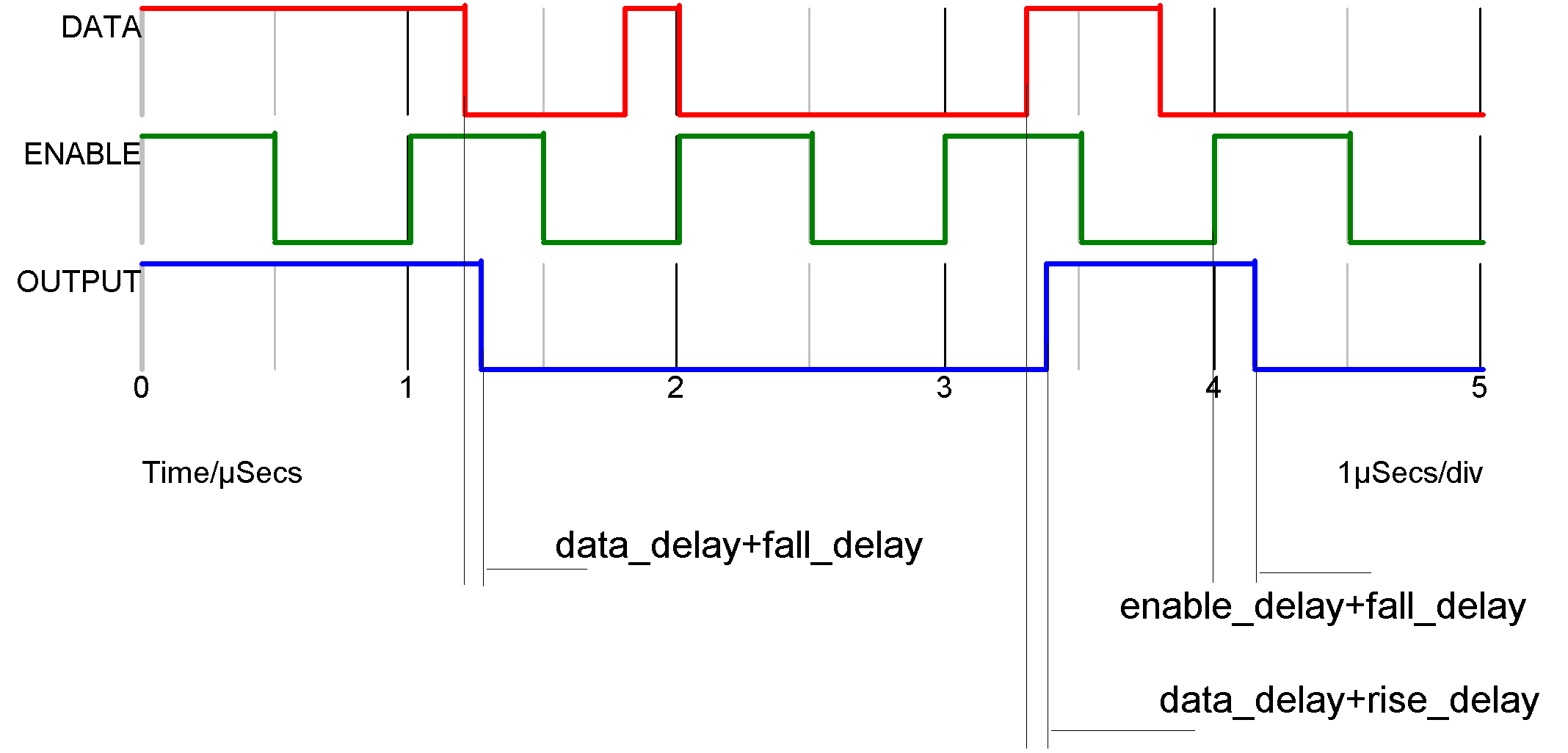
The asynchronous inputs (set and reset) override the action of the enable and data lines.
| ◄ And Gate | D-type Flip Flop ▶ |