6.2 Using the Change() Function
In 6.1 Using the Var() and GlobalVar() Functions, you learned how to add variables to the symbol properties and then how to use the Var() and GlobalVar() functions to set the variable values. Now that you understand the Var() and GlobalVar() syntax, you will use the Change() function to produce a testplan equivalent to the 6.1_globalvar.testplan by using a syntax similar to the Var() and GlobalVar() functions to change the values directly on the schematic.
In this topic:
6.2.1 Changing Values on Top-Level Symbols
To change values on top-level symbols, follow these steps:
- Open the testplan from SIMPLIS_dvm_tutorial_examples.zip at this path: testplans/6.1_globalvar.testplan.
- In the header row, replace GlobalVar with C hange.
- Change the variables L1_val and C1_val to the reference designators
of the symbols, L1 and C1, respectively. Result: Your testplan should now look like the following with the modifications in red This testplan is available from SIMPLIS_dvm_tutorial_examples.zip at this path: testplans/6.2_change_top_level_values.testplan.
| 1 | *** | |||||||
|---|---|---|---|---|---|---|---|---|
| 2 | *** 6.2_change_top_level_values.testplan: change testplan for DVM tutorial section 6.2 | |||||||
| 3 | *** | |||||||
| 4 | *?@ Analysis | Objective | Change(L1, 2.2u) | Change(C1, 10u) | Source | Load | Label | |
| 5 | *** | |||||||
| 6 | Ac | BodePlot(OUTPUT:1) | Source(INPUT:1, Nominal) | Load(OUTPUT:1, Light) | Default Values|Bode Plot|Vin Nominal|Light Load | |||
| 7 | Ac | BodePlot(OUTPUT:1) | Source(INPUT:1, Nominal) | Load(OUTPUT:1, 50%) | Default Values|Bode Plot|Vin Nominal|50% Load | |||
| 8 | Ac | BodePlot(OUTPUT:1) | Source(INPUT:1, Nominal) | Load(OUTPUT:1, 100%) | Default Values|Bode Plot|Vin Nominal|100% Load | |||
| 9 | *** | |||||||
| 10 | *** these tests use the new modified values | |||||||
| 11 | b | |||||||
| 12 | Ac | BodePlot(OUTPUT:1) | 1.8u | 12.5u | Source(INPUT:1, Nominal) | Load(OUTPUT:1, Light) | New Values|Bode Plot|Vin Nominal|Light Load | |
| 13 | Ac | BodePlot(OUTPUT:1) | 1.8u | 12.5u | Source(INPUT:1, Nominal) | Load(OUTPUT:1, 50%) | New Values|Bode Plot|Vin Nominal|50% Load | |
| 14 | Ac | BodePlot(OUTPUT:1) | 1.8u | 12.5u | Source(INPUT:1, Nominal) | Load(OUTPUT:1, 100%) | New Values|Bode Plot|Vin Nominal|100% Load | |
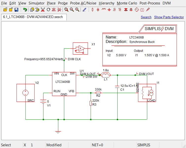
When one of the tests in lines 12-14 of the testplan above runs on the schematic, LTC3406B/6.1_LTC3406B - DVM ADVANCED.sxsch, the values on the schematic change from the variable names {L1_val} and {C1_val} to the values in the testplan, 1.8u and 12.5u. The variable statements in the F11 window are deleted, and the schematic is configured as the one below which is available from SIMPLIS_dvm_tutorial_examples.zip at this path:
LTC3406B/6.2_LTC3406B - DVM ADVANCED.sxsch.
6.2.2 Changing Other Top-Level Properties
Both symbols and hierarchical components can have multiple properties. For example L1 is a lossy inductor defined as a subcircuit. The lossy inductor model has properties for the shunt and series resistances as well as the inductance.
Before you can use the Change() function to alter these values on the schematic, you need to identify the address of these other properties. A property address consists of the reference designator and the property name separated by a period. For example, the property address of the L1 RSERIES property is L1.RSERIES.
To examine these other properties on the schematic, follow these steps:
- Open the schematic from SIMPLIS_dvm_tutorial_examples.zip at this path: LTC3406B/6.2_LTC3406B - DVM ADVANCED.sxsch.
- Right click on the L1 symbol and from the context menu option,select
Edit/Add Properties....
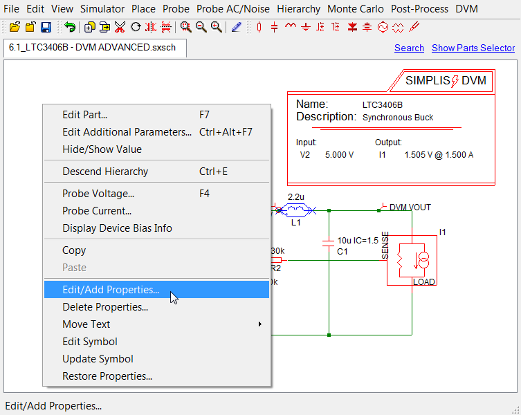 Result: The Edit/Add Properties dialog box shows each property name and its corresponding value in a two-column format as shown below.
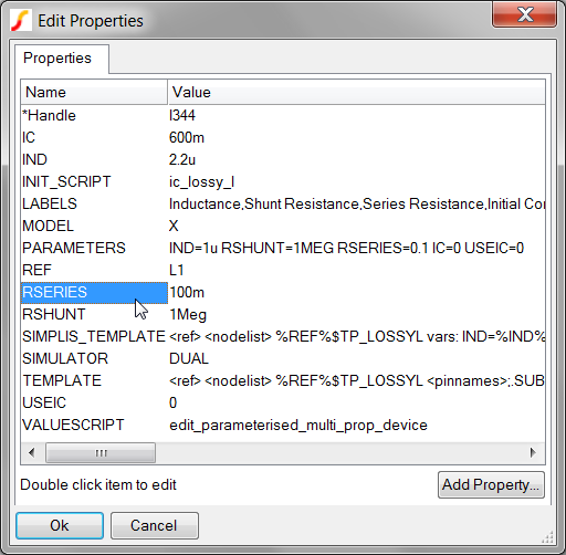
To modify the testplan to use the change function for the L1 RSERIES property, follow these steps:
- Open the following testplan from SIMPLIS_dvm_tutorial_examples.zip at this path: testplans/6.2_change_top_level_values.testplan.
- In the header column with the first Change() function, replace L1 with L1.RSERIES and replace 2.2u with 100m.
- In lines 12 - 14 in that same column, change 1.8u to 50m. Result: The testplan shown below is available from SIMPLIS_dvm_tutorial_examples.zip at this path: testplans/6.2_change_property_address.testplan.
| *** | ||||||
|---|---|---|---|---|---|---|
| *** 6.2_change_property_address.testplan: property address change testplan for DVM tutorial section 6.2 | ||||||
| *** | ||||||
| *?@ Analysis | Objective | Change(L1.RSERIES, 100m) | Change(C1, 10u) | Source | Load | Label |
| *** | ||||||
| Ac | BodePlot(OUTPUT:1) | Source(INPUT:1, Nominal) | Load(OUTPUT:1, Light) | Default Values|Bode Plot|Vin Nominal|Light Load | ||
| Ac | BodePlot(OUTPUT:1) | Source(INPUT:1, Nominal) | Load(OUTPUT:1, 50%) | Default Values|Bode Plot|Vin Nominal|50% Load | ||
| Ac | BodePlot(OUTPUT:1) | Source(INPUT:1, Nominal) | Load(OUTPUT:1, 100%) | Default Values|Bode Plot|Vin Nominal|100% Load | ||
| *** | ||||||
| *** these tests use the new modified values | ||||||
| *** | ||||||
| Ac | BodePlot(OUTPUT:1) | 50m | 12.5u | Source(INPUT:1, Nominal) | Load(OUTPUT:1, Light) | New Values|Bode Plot|Vin Nominal|Light Load |
| Ac | BodePlot(OUTPUT:1) | 50m | 12.5u | Source(INPUT:1, Nominal) | Load(OUTPUT:1, 50%) | New Values|Bode Plot|Vin Nominal|50% Load |
| Ac | BodePlot(OUTPUT:1) | 50m | 12.5u | Source(INPUT:1, Nominal) | Load(OUTPUT:1, 100%) | New Values|Bode Plot|Vin Nominal|100% Load |
6.2.3 Changing Lower-Level Properties
In 6.1 Using the Var() and GlobalVar() Functions, you used the GlobalVar() function to set variables available at all levels of the hierarchy. You can also use the Change() function to modify symbol property values in lower levels of the hierarchy. To do this, you need to identify the hierarchical property address, which is unique for each symbol.
The hierarchical property address is a list of reference designators and the actual property with these items separated by a period. This is the same syntax that you used for the top level L1.RSERIES. In this case, since no other reference designators exist before L1, the entire hierarchical property address is L1.RSERIES.
To identify the hierarchical property of other components, follow these steps:
- Open the schematic from SIMPLIS_dvm_tutorial_examples.zip at this path: LTC3406B/6.2_LTC3406B - DVM ADVANCED.sxsch.
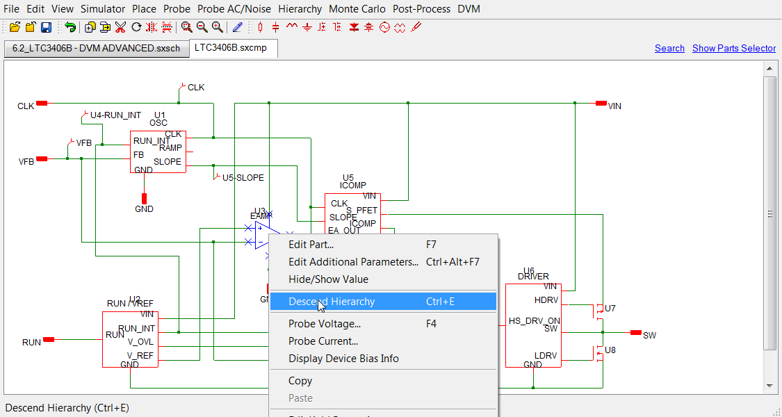
- Select the LTC3406B block, which has the reference designator U1, and press
the keyboard shortcut Ctrl E, or right-click on the block and select
Descend Hierarchy from the context menu.
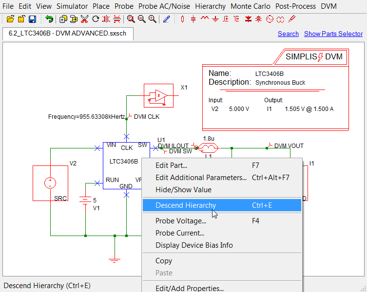 Result: The first level of the LTC3406B opens in another tab in the schematic editor.
 - To descend to the next level, select the EAMP (U3) symbol, and press the
keyboard shortcut Ctrl E, or right-click on the block and select Descend
Hierarchy from the context menu.
 Result: In the lower left portion of the schematic window at this level is the hierarchical property address U1.U3 as outlined with the red box below:
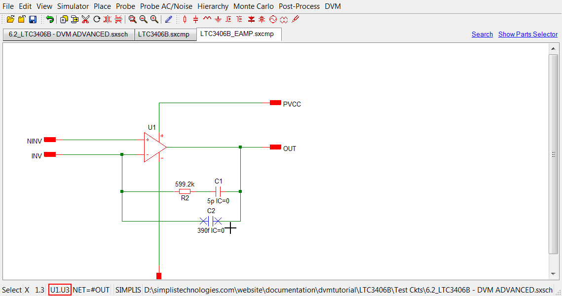
- To change the value of C2 on this schematic, append C2 to the path noted at the bottom of the schematic to define this address to U1.U3.C2.
- Open the testplan from SIMPLIS_dvm_tutorial_examples.zip at this path: testplans/6.2_change_property_address.testplan.
- In the column with the second Change() function, replace C1 with U1.U3.C2 and replace 11.5u with 390f.
- In the last three lines (12-14) in that same column, change 10u to
450f. Result: The final testplan shown below with modifications in red demonstrates both the top level property address L1.RSERIES, and the hierarchical property address U1.U3.C2. This testplan is available from SIMPLIS_dvm_tutorial_examples.zip at this path:testplans/6.2_change_hierarchical_property_address.testplan
| *** | ||||||
|---|---|---|---|---|---|---|
| *** 6.2_change_hierarchical_property_address.testplan: hierarchical property address change testplan for DVM tutorial section 6.2 | ||||||
| *** | ||||||
| *?@ Analysis | Objective | Change(L1.RSERIES, 100m) | Change(U1.U3.C2, 390f) | Source | Load | Label |
| *** | ||||||
| Ac | BodePlot(OUTPUT:1) | Source(INPUT:1, Nominal) | Load(OUTPUT:1, Light) | Default Values|Bode Plot|Vin Nominal|Light Load | ||
| Ac | BodePlot(OUTPUT:1) | Source(INPUT:1, Nominal) | Load(OUTPUT:1, 50%) | Default Values|Bode Plot|Vin Nominal|50% Load | ||
| Ac | BodePlot(OUTPUT:1) | Source(INPUT:1, Nominal) | Load(OUTPUT:1, 100%) | Default Values|Bode Plot|Vin Nominal|100% Load | ||
| *** | ||||||
| *** | ||||||
| *** | ||||||
| Ac | BodePlot(OUTPUT:1) | 50m | 450f | Source(INPUT:1, Nominal) | Load(OUTPUT:1, Light) | New Values|Bode Plot|Vin Nominal|Light Load |
| Ac | BodePlot(OUTPUT:1) | 50m | 450f | Source(INPUT:1, Nominal) | Load(OUTPUT:1, 50%) | New Values|Bode Plot|Vin Nominal|50% Load |
| Ac | BodePlot(OUTPUT:1) | 50m | 450f | Source(INPUT:1, Nominal) | Load(OUTPUT:1, 100%) | New Values|Bode Plot|Vin Nominal|100% Load |
When this testplan is run on the schematic LTC3406B/6.2_LTC3406B - DVM ADVANCED.sxsch from SIMPLIS_dvm_tutorial_examples.zip , DVM descends for each test into U1, then into U3 and changes the component value for C2. The program then ascends to the top level and executes the simulation.
Also, if you save a DVM schematic after running a DVM testplan, the schematic saves the component values in the current (changed) state of the circuit. The actual changes made to your schematic depend on which tests were run.