6.3 Using Jumpers
Sections 6.1 Using the Var() and GlobalVar() Functions and 6.2 Using the Change() Function explained the use of the Var(), GlobalVar(), and Change() functions to modify components on the schematic. This section explains how to use jumpers to make schematic topology changes that cannot be implemented by changing the value of components.
The jumper symbols have either one or two positions and can have up to 64 poles. Through the testplan, jumper positions can be changed on a test-by-test basis to provide additional flexibility in configuring the schematic.
The process for using jumpers consists of two basic additions to the testplan.
- Inserting a column with a Change() function in the header.
- In each test row for that column, adding an Open() or Close() function with a
list of jumper reference designators, using the following syntax for the
one-position jumper:
- Open(refdes1, refdes2,...refdesn)
- Close(refdes1, refdes2,...refdesn)
- If you use two-position jumpers, the syntax is the same, but you use the
following functions:
- Open(refdes1, refdes2,...refdesn)
- Pos1(refdes1, refdes2,...refdesn)
-
Pos2(refdes1, refdes2,...refdesn)
where Close() is a synonym for Pos1().
6.3.1 Editing the Schematic
To change the schematic using jumpers, follow these steps:
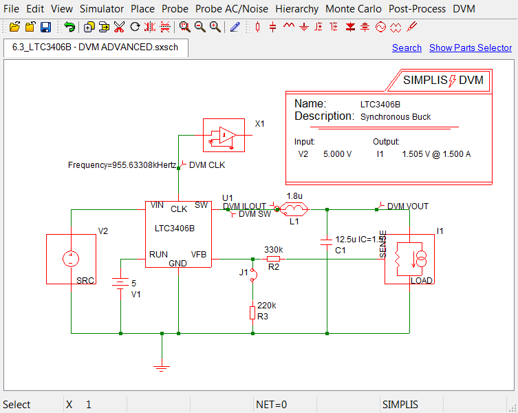
- Open the schematic from SIMPLIS_dvm_tutorial_examples.zip at this path: LTC3406B/6.2_LTC3406B - DVM ADVANCED.sxsch.
- Move the feedback resistor R3 down to make room for the jumper, and delete the vertical line between R3 and the horizontal line.
- From the parts selector, choose .
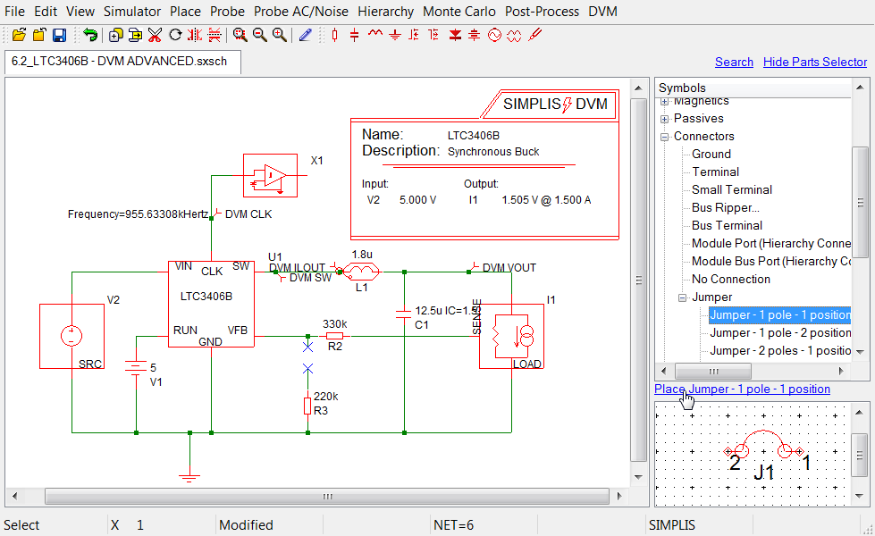
- Press F5 to rotate the jumper 90 degrees; press F6 to flip it; and then click to place the jumper and connect it to R3.
- Draw a line to connect the jumper to the line between R2 and the LTC3406B. Result: The correctly configured schematic shown below is available from SIMPLIS_dvm_tutorial_examples.zip at this path: LTC3406B/6.3_LTC3406B - DVM ADVANCED.sxsch
6.3.2 Editing the Testplan
To control the jumpers from the testplan, follow these steps to edit the testplan available from SIMPLIS_dvm_tutorial_examples.zip at this path: testplans/6.1_var_start.testplan.
- Change the title in line 2 to Jumpers testplan: Jumper testplan for DVM tutorial section 6.3.
- Copy lines 5-9 and paste them below the last line of the testplan so that you have six tests.
- Add the following to the comment in line 10: *** the jumper position sets the output voltage to 0.6V.
- Insert a column between Objective and Source, and label the new column Jumper.
- Make the changes listed below:
Rows Column Text to replace Text to add 6-8 jumper Close(J1) 6-8 label Default values VOUT=1.505V 12-14 jumper Open(J1) 12-14 label Default values VOUT=600mV Result: Your schematic should now look like the following with the above modifications highlighted in red. A version of this testplan is available from SIMPLIS_dvm_tutorial_examples.zip at this path: testplans/6.3_jumpers.testplan.
| *** | ||||||
|---|---|---|---|---|---|---|
| *** 6.3_jumpers.testplan: Jumper testplan for DVM tutorial section 6.3 | ||||||
| *** | ||||||
| *?@ Analysis | Objective | Jumper | Source | Load | Label | |
| *** | ||||||
| Ac | BodePlot(OUTPUT:1) | Close(J1) | Source(INPUT:1, Nominal) | Load(OUTPUT:1, Light) | VOUT=1.505V |Bode Plot|Vin Nominal|Light Load | |
| Ac | BodePlot(OUTPUT:1) | Close(J1) | Source(INPUT:1, Nominal) | Load(OUTPUT:1, 50%) | VOUT=1.505V |Bode Plot|Vin Nominal|50% Load | |
| Ac | BodePlot(OUTPUT:1) | Close(J1) | Source(INPUT:1, Nominal) | Load(OUTPUT:1, 100%) | VOUT=1.505V |Bode Plot|Vin Nominal|100% Load | |
| *** | ||||||
| *** the jumper position sets the output voltage to 0.6V | ||||||
| *** | ||||||
| Ac | BodePlot(OUTPUT:1) | Open(J1) | Source(INPUT:1, Maximum) | Load(OUTPUT:1, Light) | VOUT=0.6V |Bode Plot|Vin Maximum|Light Load | |
| Ac | BodePlot(OUTPUT:1) | Open(J1) | Source(INPUT:1, Maximum) | Load(OUTPUT:1, 50%) | VOUT=0.6V |Bode Plot|Vin Maximum|50% Load | |
| Ac | BodePlot(OUTPUT:1) | Open(J1) | Source(INPUT:1, Maximum) | Load(OUTPUT:1, 100%) | VOUT=0.6V |Bode Plot|Vin Maximum|100% Load | |
After executing a single test from each group of tests, the overview report shows the test in the first set as "passed" with the default output voltage of 1.505V. The test in the second set with an output voltage of 600mV fails since the output voltage specifications were not changed in the control symbol when you used the jumper to change the output voltage setpoint.
You can include as many jumper reference designators as necessary using a comma between each designator in the list. For more information, see Jumpers in the DVM documentation.