Digital Gate
Here is a definition for an AND gate
'include "disciplines.vams"

module and_gate(in1, in2, out);

electrical in1, in2, out ;

parameter real  digThresh = 2.0,
digOutLow = 0.0,
digOutHigh = 5.0,
trise=10n,
tfall=10n ;

analog
begin : main

integer dig1, dig2, logicState ;

// Detect in1 threshold
@ (cross(V(in1)-digThresh, 0, 1n))
if (V(in1)>digThresh)
dig1 = 1 ;
else
dig1 = 0 ;

// Detect in2 threshold
@ (cross(V(in2)-digThresh, 0, 1n))
if (V(in2)>digThresh)
dig2 = 1 ;
else
dig2 = 0 ;

logicState = dig1 && dig2 ? digOutHigh : digOutLow ;
V(out) <+ transition(logicState , 0.0, trise, tfall) ;
end
endmodule
- The cross event
- The transition analog operator
In this topic:
cross() Monitored Event
The cross event function is used to detect when an input signal crosses its logic threshold. Consider the line:
@ (cross(V(in1)-digThresh, 0, 1n))
This line both defines the event and also responds to the event when it is triggered. The arguments define the event, while the statement that follows it is the action taken when the event is triggered.
The function has the following form:
cross( expr, edge, time_tol, expr_tol )
Only the first argument is compulsory.
| expr | expression to test. The event is triggered when the expression crosses zero. |
| edge | 0, +1 or -1 to indicate edge. +1 means the event will only occur when expr is rising, -1 means it will only occur while falling and 0 means it will occur on either edge. Default=0 if omitted. |
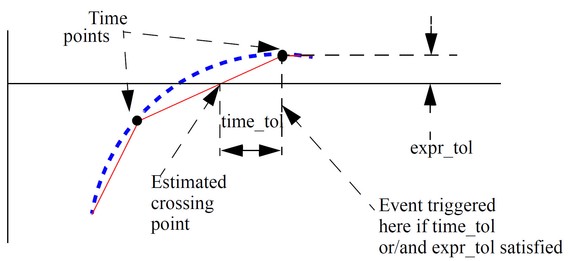
| time_tol | Time tolerance for detection of zero crossing. Unless the input is moving in an exact linear fashion, it is not possible for the simulator to predict the precise location of the crossing point. But it can make an estimate and then cut or extend the time step to hit it within a defined tolerance. time_tol defines the time tolerance for this estimate. The event will be triggered when the difference between the current time step and the estimated crossing point is less than time_tol. If omitted or zero or negative, no timestep control will be applied and the event will be triggered at the first natural time point after the crossing point. See diagram below for an illustration of the meaning of this parameter. |
| expr_tol | Similar to time_tol but instead defines the tolerance on the input expression. See dialog below. |
 |
Cross Event Function Behaviour |
transition() Analog Operator
The transition function at the end is one of a class of functions called analog operators. The ddt and idt functions seen earlier are also analog operators. The transition analog operator is designed to handle signals that change in discrete steps such as the output of logic devices and digital to analog converters. In the and gate example above, the output logic level can change instantaneously but the output of a real device would typically follow a specified rise or fall time. The transition analog operator converts the discrete input value to a continuous output value using specified rise and fall times. The function has the following form:
transition(expr, td, rise_time, fall_time, time_tol)
| expr | Input expression. |
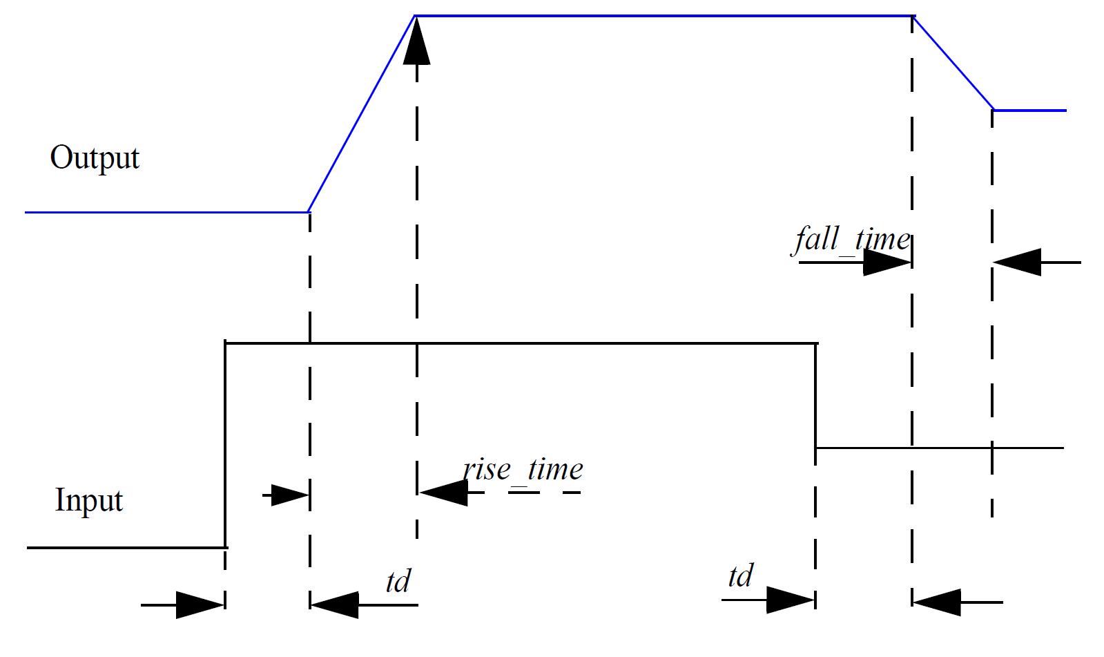
| td | Delay time. This is a transport or stored delay. That is, all changes will be faithfully reproduced at the output after the specified delay time, even if the input changes more than once during the delay period. This is in contrast to intertial delay which swallows activity that has a shorter duration than the delay. Default=0. |
| rise_time | Rise time of output in response to change in input. |
| fall_time | Fall time of output in response to change in input. |
| time_tol | Ignored. The LRM does not explicitly state what this is supposed to do and we see no purpose for a tolerance parameter. |
If fall_time is omitted and rise_time is specified, the fall_time will default to rise_time. If neither is specified or are set to zero, a minimum but non-zero rise/fall time is used. This is set to the value of MINBREAK which is the minimum break point value. Refer .OPTIONS in the Simulator Reference Manual/Command Reference/.OPTIONS for details of MINBREAK.
The transition analog operator should not be used for continuously changing input values; use the slew or absdelay analog operators instead.
 |
Transition Analog Operator Waveforms |
| ◄ Digital Elements - Overview | Butterworth Filter ▶ |