Resistor - Hspice Compatible
In this topic:
Netlist Entry
Rxxxx n1 n2 [model_name] [value] [L=length] [W=width] [AC=ac_resistance] [TC1=tc1]
[TC2=tc2] [M=mult] [SCALE=scale] [DTEMP=dtemp] [C=c]
| model_name | Name of .MODEL. This is compulsory unless this model made the default resistor. See Making the Hspice Resistor the Default. |
| value | Value of resistor. This may be an expression relating parameters defined using .PARAM and circuit variables in the form V(n1,n2) and I(device). Expressions must be enclosed in curly braces or quotation marks. Typically the expression relates to the resistor's own terminals in order to define voltage dependence |
| length | Length in metres |
| width | Width in metres |
| ac_resistance | Value of resistor for AC analyses. Like the main value, this may also be an expression. See above under value for details |
| tc1 | First order temperature coefficient |
| tc2 | Second order temperature coefficient |
| mult | Device multiplier. Equivalent to putting mult devices in parallel, but note that this value does not have to be integral |
| scale | Scales resistance and capacitance values. E.g. Reff=scale*R |
| dtemp | Differential temperature. Device temperature = global temperature + dtemp |
| c | Capacitance to reference node |
Resistor Model Syntax
.model modelname R (LEVEL=2 parameters )
| Name | Description | Units | Default |
| BULK | Bulk connection for capacitance | Ground | |
| CAP | Device capacitance | F | 0.0 |
| CAPSW | Sidewall capacitance | F/m | 0.0 |
| COX | Capacitance per unit area | F/m2 | 0.0 |
| CRATIO | Capacitance terminal distribution | 0.5 | |
| DI | Dielectric constant | 0.0 | |
| DL | Difference between drawn length and actual length for capacitance calculation | m | DW |
| DLR | Difference between drawn length and actual length for resistance calculation | m | 0.0 |
| DW | Difference between drawn width and actual width | m | 0.0 |
| L, ML | Length | m | 0.0 |
| W, MW | Width | m | 0.0 |
| NOISE | Noise multiplier | 1.0 | |
| RAC | AC resistance | Ω | |
| RES | Resistance | Ω | 0.0 |
| RSH | Sheet resistance | Ω/sq | 0.0 |
| SHRINK | Shrink factor | 1.0 | |
| TC1C | Capacitance first order temperature coefficient | 1/C | 0.0 |
| TC1R | Resistance first order temperature coefficient | 1/C | 0.0 |
| TC2C | Capacitance second order temperature coefficient | 1/C2 | 0.0 |
| TC2R | Resistance second order temperature coefficient | 1/C2 | 0.0 |
| THICK | Dielectric thickness | m | 0.0 |
| TREF | Measurement temperature | C | TNOM |
| ACRESMOD | AC resistance model selector. See ACRESMOD Parameter | 0 | |
| KF | Flicker noise coefficient | 0 | |
| AF | Flicker noise current exponent | 2.0 | |
| LF | Flicker noise length exponent | 1.0 | |
| WF | Flicker noise width exponent | 1.0 | |
| EF | Flicker noise frequency exponent | 1.0 |
Resistance Calculation
In the following reff is the effective non-temperature adjusted resistance used for DC analyses, reffac is the effective non-temperature adjusted resistance used for AC analyses.
If instance resistance is specified:
reff = value * SCALE/Motherwise if weff*leff*RSH>0
reff = SCALE*RSH*leff / (weff*M)where:
weff = SHRINK*W - 2*DW
leff = SHRINK*L - 2*DLRotherwise
reff = SCALE*RES/MIf instance AC parameter is specified:
raceff = AC*SCALE/Motherwise if RAC given
raceff = SCALE*RAC/Motherwise
raceff = reff
Capacitance Calculation
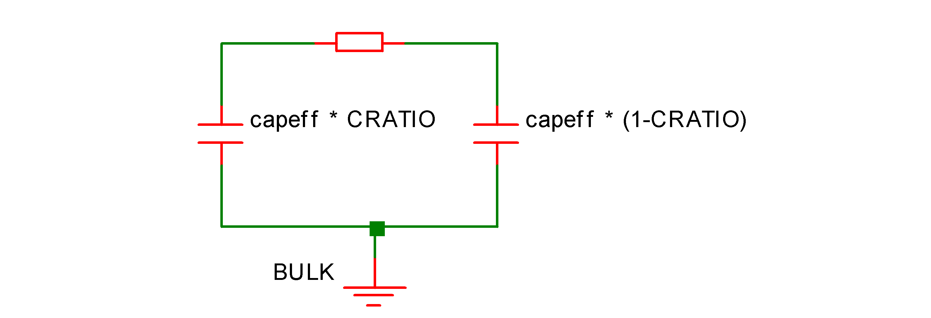
capeff is the non temperature adjusted capacitance.
If instance parameter C is given:
capeff = M*SCALE*Cotherwise if model parameter CAP is given
capeff = M*SCALE*CAPotherwise
capeff = (leffc*weffc*coxmod + 2*((leffc+weffc)*CAPSW))*M*SCALEwhere:
leffc = SHRINK*L - 2*DL
weffc = SHRINK*W - 2*DWSee below for coxmod calculation.
Calculation of COX
If COX given
coxmod = COXotherwise if THICK <> 0 AND DI<>0
coxmod = 8.8542149e-012*DI/THICKotherwise if THICK <> 0 AND DI=0
coxmod = 3.453148e-011/THICKotherwise
coxmod = 0.0
Temperature Scaling
Resistance
R(t) = reff * tscalewhere:
tscale = 1+(tc1inst+tdelta*tc2inst)*tdeltawhere
tdelta = tinst-TREF-273.15
tc1inst = if instance TC1 given: TC1 else TC1R
tc2inst = if instance TC2 given: TC2 else TC2R
tinst = [global circuit temperature] + DTEMP (Kelvin)
Capacitance
C(t) = capeff * tscalewhere
tcscale = 1+(TC1C+tdelta*TC2C)*tdeltatdelta defined above.
Flicker Noise
\[ I_n = \frac{\text{KF} \times I^{\text{AF}}}{L_{\text{eff}}^{\text{LF}} \times W_{\text{eff}}^{\text{WF}} \times f^{\text{EF}}} \]
ACRESMOD Parameter
This parameter controls the calculation of resistance in AC analysis. With ACRESMOD=0 AC analysis uses the large signal resistance value, that is the value of resistance calculated during the DC analysis. If ACRESMOD=1, the small signal resistance is used, that is, the value of dv/di at the operating point. If the resistance is defined as an expression containing circuit variables (i.e. it is voltage dependent), the large signal resistance is different to the small signal resistance.
This resistor model has been developed primarily for compatibility with Hspice models. Hspice itself always uses the large signal resistance. However, this will create a discrepancy between AC analysis and a transient analysis of a small signal. To resolve this discrepancy, set ACRESMOD to 1.
In summary, to be compatible with Hspice, use ACRESMOD=0, for consistent results between AC and transient analyses, use ACRESMOD=1.
In noise analysis the large signal value is always used.
Making the Hspice Resistor the Default
This resistor model requires the specification of a model name and the creation of a .MODEL statement with LEVEL=2. This is likely to be inconvenient if a model file containing Hspice resistors is being used.
To overcome this, the HSPICEMODELS option setting may be used to make this resistor the default. Add this line to the netlist:
.OPTIONS HSPICEMODELS=1
.OPTIONS HSPICECOMPATIBILITY=1
See .OPTIONS for more details
| ◄ Resistor | CMC Resistor ▶ |