Digital-Analog Converter
In this topic:
Netlist entry
Axxxx [ digital_in_0 digital_in_1 .. digital_in_n ]
+ analog_out model_name
Connection details
| Name | Description | Flow | Type | Allowed types | Vector bounds |
| digital_in | Data output | in | d | d | 1 - 32 |
| analog_out | Analog output | out | v | v, vd, i, id | n/a |
Model format
.MODEL model_name da_converter parameters
Model parameters
| Name | Description | Type | Default | Limits |
| output_offset | Offset voltage | real | 0 | none |
| output_range | Input signal range | real | 1 | none |
| twos_complement | Use 2's complement input. (Default is offset binary) | boolean | FALSE | none |
| output_slew_time | Output slew time | real | 10nS | ???MATH???1\text{e}^{-12} - \infty???MATH??? |
| in_family | Input logic family | string | UNIV | none |
| input_load | Input load | real | 1pF | ???MATH???0 - \infty???MATH??? |
| sink_current | Input sink current | real | 0 | none |
| source_current | Input source current | real | 0 | none |
Device Operation
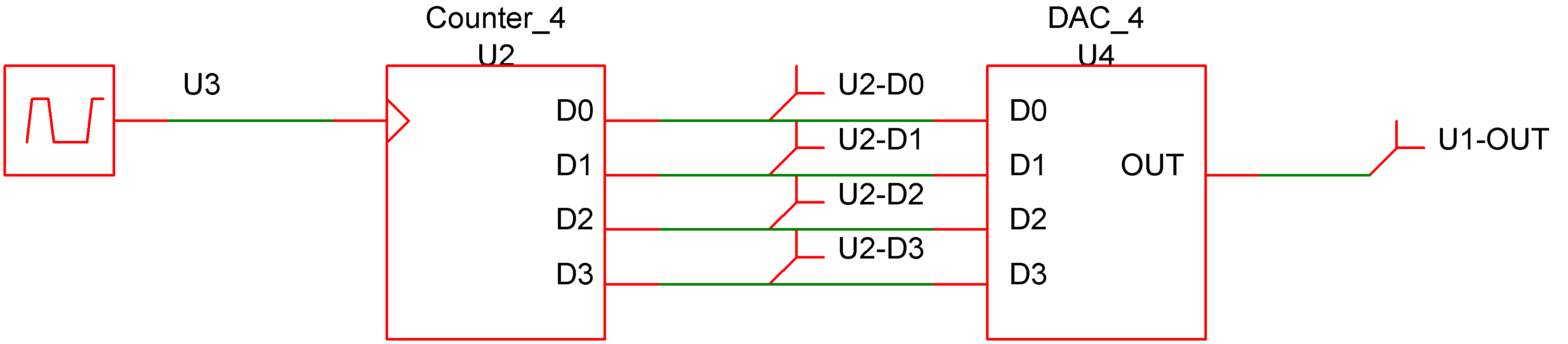
This device is a 1-32 bit digital to analog converter. Its operation is illustrated by the following diagrams.
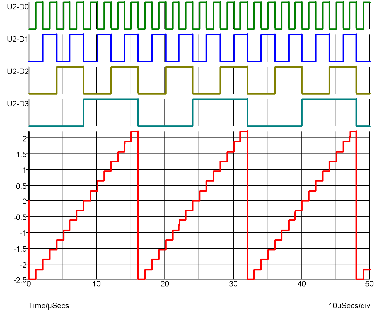 |
DAC Waveforms |
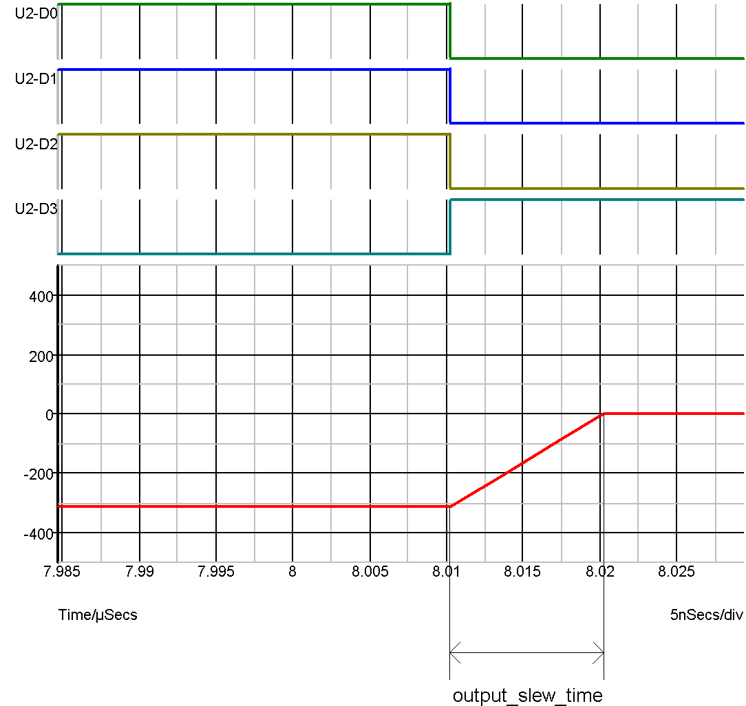 |
DAC waveforms expanded to show output slew |
The device illustrated above has the following model definition:
.model DAC_4 da_converter
+ output_slew_time 1e-08
+ output_range 5
+ output_offset 0
In offset binary mode the D-A converter produce an output voltage equal to:
-OUTPUT_RANGE/2 + OUTPUT_OFFSET + code * OUTPUT_RANGE/2 n
where n is the number of bits and code is the digital input code represented as an unsigned number between 0 and ???MATH???2^{n}-1???MATH???.
In 2's complement mode the output is:
OUTPUT_OFFSET + code * OUTPUT_RANGE/2 n
where n is the number of bits and code is the digital input code represented as a signed number between ???MATH???-2^{n/2}???MATH??? and ???MATH???2^{n/2}-1???MATH???.
Whenever the input code changes, the output is set on a trajectory to reach the target value in the time specified by OUTPUT_SLEW_TIME. UNKNOWN states are ignored. That is the input will be assumed to be at the most recent known state.
| ◄ Analog-Digital Interface Bridge | Digital-Analog Interface Bridge ▶ |