Frequency Divider

In this topic:
Netlist entry
Axxxx freq_in freq_out model_name
Connection details
| Name | Description | Flow | Type |
| freq_in | Frequency input | in | d |
| freq_out | Frequency output | out | d |
Model format
.MODEL model_name d_fdiv parameters
Model parameters
| Name | Description | Type | Default | Limits |
| div_factor | Divide factor | integer | 2 | ???MATH???1 - \infty???MATH??? |
| high_cycles | Number of high clock cycles | integer | 1 | ???MATH???1 - \infty???MATH??? |
| i_count | Output initial count value | integer | 0 | ???MATH???0 - \infty???MATH??? |
| rise_delay | Rise delay | real | 1nS | 1e-12 ???MATH???- \infty???MATH??? |
| fall_delay | Fall delay | real | 1nS | 1e-12 ???MATH???- \infty???MATH??? |
| freq_in_load | Freq_in load value (F) | real | 1pF | none |
| family | Logic family | string | UNIV | none |
| in_family | Input logic family | string | UNIV | none |
| out_family | Output logic family | string | UNIV | none |
| out_res | Digital output resistance | real | 100 | ???MATH???0 - \infty???MATH??? |
| out_res_pos | Digital output res. pos. slope | real | out_res | ???MATH???0 - \infty???MATH??? |
| out_res_neg | Digital output res. neg. slope | out_res | ???MATH???0 - \infty???MATH??? | |
| min_sink | Minimum sink current | real | -0.001 | none |
| max_source | Maximum source current | real | 0.001 | none |
| sink_current | Input sink current | real | 0 | none |
| source_current | Input source current | real | 0 | none |
Device Operation
This device is a positive edge triggered frequency divider. Three model parameters allow arbitrary definition of the divide ratio, output duty cycle, output phase and initial delay. Operation of the frequency divider is illustrated by the following diagram which shows the output of a frequency divider with a DIV_FACTOR of 10 and two alternative values of HIGH_CYCLES.
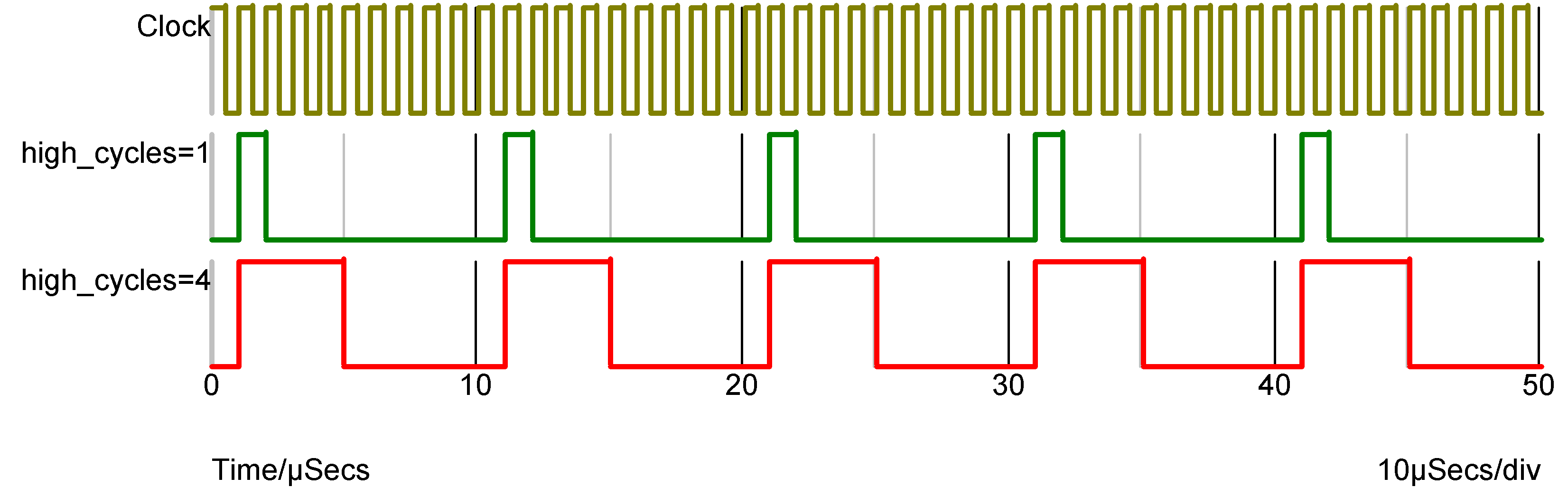
The above was carried out with I_COUNT=0. I_COUNT is the initial value of the internal counter. The output first goes high when it attains a value of 1 or 1+DIVIDE_RATIO so when I_COUNT is zero (the default) the output first goes high after the first rising edge. If I_COUNT is set to 5 the output first goes high after the 6th rising edge and if I_COUNT is -20, the 21st rising edge.
| ◄ Buffer | Digital Initial Condition ▶ |