Circuit Stimulus
Most circuits require some form of input signal such as a pulse or sine wave. Such signals - or stimuli - are specified using a voltage or current source which is placed on the schematic in the usual way. A number of different types of source are available. These are described in the following sections.
In this topic:
Waveform Generator
This is used to create a time domain signal for transient analysis. This generator will work in both SIMetrix and SIMPLIS modes of operation. To place one of these devices, select menu for a voltage source or for a current source.
To specify the signal for the source, select then choose the popup menu Edit Part... or press F7. This will bring up the dialog box shown below. (In SIMPLIS simulation mode it will have an additional check box - see notes below)
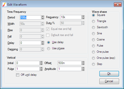
Select the wave shape on the right hand side then enter the parameters as appropriate. The following notes provide details on some of the controls.
- Damping describes an exponential decay factor for sinusoidal wave-shapes. The decay is governed by the expression: \[ e^{-\text{damping}\times t} \]
- Off until delay if checked specifies that the signal will be at the Initial value until the delay period has elapsed.
- Note that some parameters can be specified in more than one way. For example both frequency and period edit controls are supplied. Changing one will cause the other to be updated appropriately. The same applies to duty and width and the vertical controls in the lower half.
- A Cosine wave-shape combined with a positive delay and with Off until delay checked, will only function correctly in SIMPLIS mode.
- If in SIMPLIS simulation mode, you will also see a check box titled Source Idle during POP and AC analyses. If checked, the source will be disabled in POP and AC analysis modes.
PWL Source
This device can be used to describe a piece wise linear source. A PWL source can describe any arbitrary wave shape in terms of time-voltage or time-current pairs. To place a PWL source select menu or .
To edit the device, select it and press F7 or Edit Part... popup menu. This will open the Edit PWL Dialog which allows you to enter time and voltage/current values.
As well as entering values individually, you can also paste them from the Windows clipboard by pressing the Paste button or ctrl-V. The values can be copied to the clipboard using a text editor. The values may be separated by spaces, tabs, commas or new lines.
PWL sources may be used in both SIMetrix and SIMPLIS modes, but note that in SIMPLIS, PWL sources are limited to 256 points. Larger definitions are allowed in SIMetrix mode, but for very large PWL definitions, a PWLFILE source will See the "Analog Device Reference" in the Simulator Reference Manual for more information.
In SIMPLIS mode, a check box titled Source Idle during POP and AC analyses will also be shown. This will be checked by default meaning that the source is inactive in POP and AC analyses.
Power Supply/Fixed Current Source
Select menu or to place a fixed voltage or current source. These devices work in both SIMetrix and SIMPLIS modes.
AC Source
The small signal analysis modes, AC sweep and Transfer Function, require AC sources for their input stimulus.
To place an AC source select menu or .
You can also use a Universal Source (see below) for the AC source for SIMetrix (i.e. not SIMPLIS) simulations. Be sure to check the Enable AC check box in the Universal Source.
Universal Source
All of the sources described above can be used in both SIMetrix and SIMPLIS modes of operation. In SIMetrix mode there is also a Universal source which provides the function of transient, AC and DC sources all in one device. In addition, the Universal source may be used to create a random noise source.
To place a universal source, select menu or .
To edit a universal source, select the device and press F7 or popup menu Edit Part.... This will display the following dialog box:
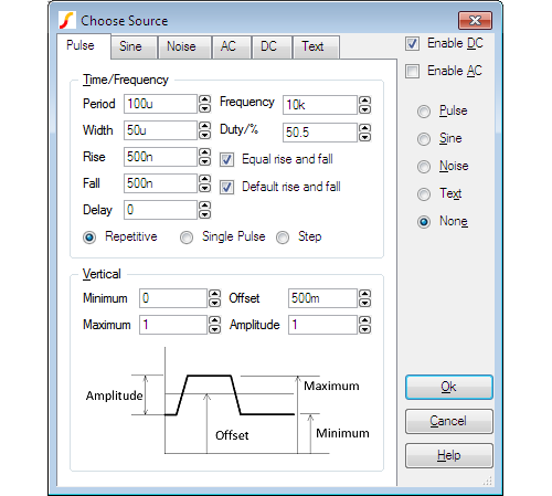
Pulse Sheet
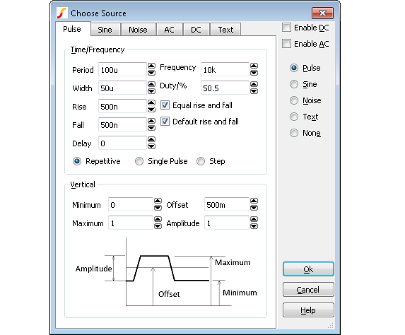
This selects the values for pulse waveform. For the values to be used the Pulse radio button at the right of the box must be selected.
The diagram below defines the pulse waveform timings.
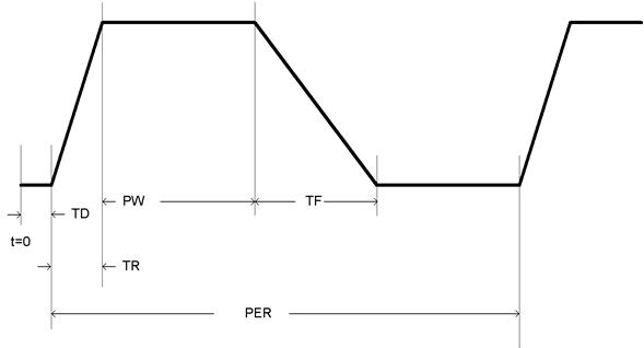
- PER = Period
- PW = Width
- TR = Rise
- TF = Fall
- TD = Delay
Period/Width and Frequency/Duty boxes are two different ways of specifying the same thing. If you modify one pair the others change accordingly.
Sine Sheet
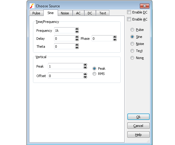
This selects values for a sine wave generator. For the values to be used the Sine radio button at the right of the box must be selected.
The shape of the waveform is described by:
0 to delay: ???MATH???voffset???MATH???
delay to Stop time ???MATH???voffset + vpeak.e^{-(t-delay).theta}).\sin(2.\pi.freq.(t+delay))???MATH???
- ???MATH???t???MATH??? : time
- ???MATH???voffset???MATH??? : value in Offset edit box
- ???MATH???vpeak???MATH??? : value in Peak edit box. If RMS is selected, ???MATH???vpeak = vrms.\sqrt{2}???MATH???
- ???MATH???delay???MATH??? : value in Delay edit box
- ???MATH???theta???MATH??? : value in Theta edit box
- ???MATH???freq???MATH??? : value in Frequency edit box
Phase is implemented using a negative delay value. For example, a phase of 30 degrees is entered, the delay will be ???MATH???30/360 . 1/freq???MATH???
Noise Sheet
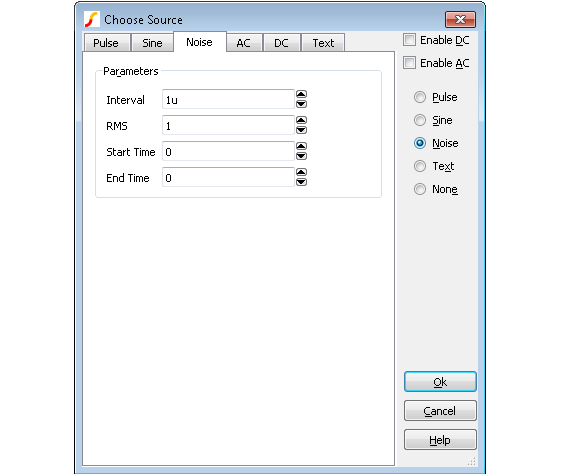
To enable noise, select the Noise radio button at the right of the dialog box.
Source generates a random value at gui{Interval} with distribution such that spectrum of signal generated is approximately flat up to frequency equal to 1/(2*interval). Amplitude of noise is RMS volts.
Start time and End time values may be entered to define the interval over which the noise signal is active. If End time is zero, the noise will continue to the end of the simulation.
AC Sheet
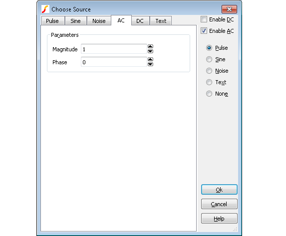
The entries in the AC sheet are only used for AC analysis.
Sets the magnitude and phase of the source for AC analysis. To take effect the Enable AC check box must be checked.
This specification has no effect in other analysis modes.
SIMetrix does not require an AC specification for the input referred source in Noise analysis.
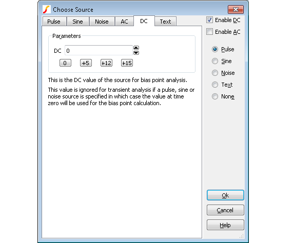
DC Sheet
Specifies DC value for bias point calculation. If one of sine, pulse, noise, piece wise linear, exponential, or single frequency fm sources is also specified, this value will be ignored and the time=0 value used instead.
Text Sheet
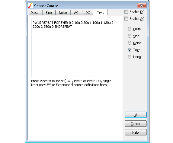
The text sheet may be used to define one of the following
The text sheet may also be used to define a single frequency FM or exponential source using traditional SPICE syntax. Refer to Simulator Reference Manual/Analog Device Reference/Voltage Source/Exponential Source and Single Frequency FM for details.
PWL Definition
An piecewise linear source may be entered in the Text Sheet of the Universal source using the syntax described below.
This applies to both voltage and current sources.
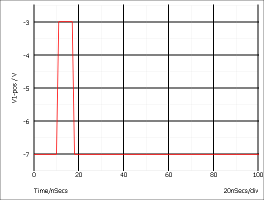
pwl ( T1 V1 [T2 V2 [T3 V3 [... ]]] )
Each pair of values (Ti Vi) specifies that the value of the source is Vi at time = Ti. The value of the source at intermediate values of time is determined by using linear interpolation on the input values.
Example
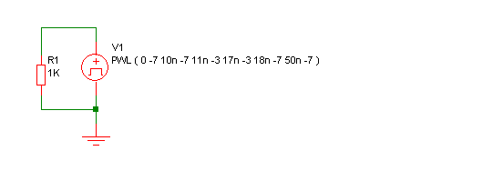
Produces this waveform:
PWLS Definition
The PWLS definition allows more advanced signal sources to be created using a simple language syntax. The syntax is described below. For some example, see PWLS Examples
The syntax is in the following form:
PWLS [TIME_SCALE_FACTOR=time_factor] [VALUE_SCALE_FACTOR=value_factor]
pwls_spec [ pwls_spec ... ]
Where:
| time_factor | Scales all time values in definition by time_factor | ||||||||||||||
| value_factor | Scales all magnitude values by value_factor | ||||||||||||||
| pwls_spec |
may be one of the following:
|
Sine Parameters
| Name | Description | Default | Compulsory |
| FREQ | Frequency | N/A | Yes |
| PEAK | Peak value of sine | 1.0 | No |
| OFFSET | Offset | 0.0 | No |
| DELAY | Delay before sine starts. | 0.0 | No |
| PHASE | Phase | 0.0 | No |
| CYCLES | Number of cycles. Use -1.0 for infinity | -1.0 | No |
| MINPOINTS | Minimum number of timesteps used per cycle | 13 | No |
| RAMP | Frequency ramp factor | 0.0 | No |
if t>0 OR DELAY<0
PEAK * SIN(f*2PI*t+PHASE*PI/180) + OFFSET
else
PEAK * SIN(PHASE*PI/180) + OFFSET
- f = FREQ + t???MATH???\times???MATH???RAMP
- t = time - tref - DELAY
- time is the global simulation time
- tref is the reference time for this spec
Pulse Parameters
| Name | Description | Default | Compulsory |
| V0 | Offset | 0 | No |
| V1 | Positive pulse value | 1.0 | No |
| V2 | Negative pules value | -1.0 | No |
| RISE | Rise time i.e time to change from V2 to V1 | PERIOD/1000 | No |
| FALL | Fall time i.e time to change from V1 to V2 | PERIOD/1000 | No |
| WIDTH | Positive pulse width | (PERIOD-RISE-FALL)/2 | No |
| PERIOD | Period | N/A | Yes |
| DELAY | Delay before start | 0 | No |
| CYCLES | Number of complete cycles. -1 means infinity | -1 | No |
PWLS Examples
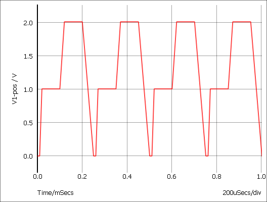
Example 1
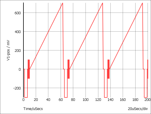
PWLS REPEAT FOREVER 0 0 10u 0 20u 1 100u 1 120u 2 200u 2 250u 0 ENDREPEATProduces a repeated signal as shown below:
Example 2
The following defines a simple grey scale PAL test signal.
PWLS REPEAT FOREVER
+ 0 0 1.65u 0 1.75u -0.3 6.35u -0.3 6.45u 0 7.3u 0
+ SIN FREQ=4.43Meg CYCLES=10 PEAK=0.1 END
+ 10u 0 63u 0.7 64u 0
+ ENDREPEAT
Example 3
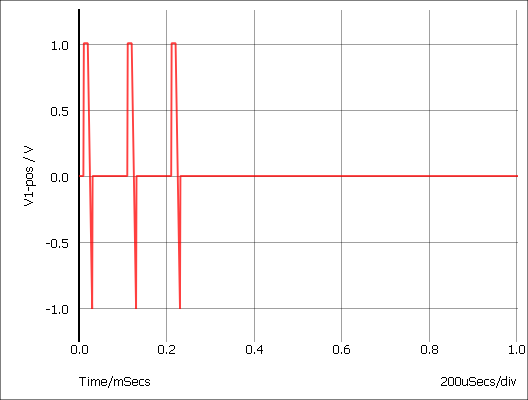
The following repeats a PWL definition 3 times only
PWLS REPEAT FOR 3 0 0 10u 0 +1u 1 20u 1 20u -1 30u -1 31u 0 100u 0 ENDREPEAT
Example 4
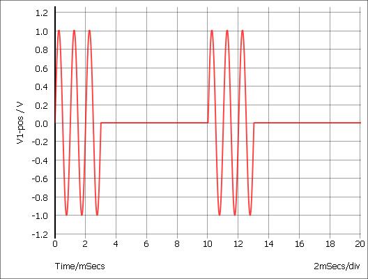
The following describes a tone burst signal
PWLS REPEAT FOREVER
+ SIN peak=1 delay=0 freq=1k cycles=3 minpoints=50 offset=0 END 0.01 0 ENDREPEAT
PWLFILE Definition
PWLFILE filename
This performs the same function as the normal piece wise linear source except that the values are read from a file named filename.
The file contains a list of time voltage pairs in text form separated by any whitespace character (space, tab, new line). It is not necessary to add the '+' continuation character for new lines but they will be ignored if they are included. Any non-numeric data contained in the file will also be ignored.
Be aware that numbers in engineering format, i.e. using suffixes such as u for 1e-6 and k for 1e3, are not recognised in a PWLFILE definition. If your data does include such values, you can instead use the PWLS definition in the form PWLS file=filename which does accept such values.
Digital Sources
Digital Pulse
The digital pulse device creates a single shot or repetitive pulse in the digital event driven domain. As digital and analog nodes can be freely interconnected, analog parts may be connected to it but it is more efficient to use an analog pulse generator for this purpose.
To Place a Digital Pulse
- Select menu or and place. The open emitter version can be "wire-ored" but requires a pull down resistor. You can use menu .
- Select device then press F7 or equivalent menu. Enter parameters as required. For a single pulse enter '0' for the period.
Device Operation This device supplies a repetitive or single pulse of defined period, delay and width. Optionally, the device may be specified to have an open emitter output allowing several pulse sources to be wire OR'ed to create complex pulses. All 5 main .MODEL parameters may also be specified on the device line as instance parameters in which case they override any values specified in the .MODEL control.
Digital Signal Source
The digital signal source provides a multi bit arbitrary digital signal defined in a file. There is no standard schematic part for this device as it can be defined with an arbitrary number of outputs. For more information, see Simulator Reference Manual/Digital Mixed Signal Device Reference/Digital Signal Source.
Other Sources
Sine Tone Burst
Generates a sequence of sinusoidal bursts with a user defined number of cycles per burst, burst frequency and tone frequency.
Use menu then place device in the usual way. Editing the device will bring up a dialog with 6 parameters:
| Parameter | Description |
| Burst Freq. | Burst frequency |
| Tone Freq. | Frequency of the sinusoidal tone |
| Num Tone Cycles | Number of sinusoidal cycles in each burst |
| Peak | Peak voltage |
| Offset | Offset voltage |
| Points Per Cycle | Minimum number of time steps in each sinusoidal cycle. Increasing this number will improve the accuracy of the simulation at the expense of simulation speed |
Swept Sinusoid
Generate a sinusoidal signal with linearly increasing frequency.
Use menu then place in the usual manner. Editing the device will bring up a dialog with 6 parameters:
| Parameter | Description |
| Start Frequency | Starting frequency |
| End Frequency | Frequency at the end of the ramp |
| Interval | Time taken to ramp from start frequency to end frequency |
| Peak | Peak voltage |
| Offset | Offset voltage |
| Points Per Cycle | Minimum number of time steps in each sinusoidal cycle. Increasing this number will improve the accuracy of the simulation at the expense of simulation speed |
Bidirectional Pulse
Generates a symmetrical bidirectional pulse waveform.
Use menu then place device in the usual way. Editing the device will bring up a dialog with 3 parameters:
| Parameter | Description |
| P-P Voltage | Peak to peak voltage |
| Frequency | Pulse frequency |
| Delay | Delay after start |
| ◄ Numbered Parts in SIMPLIS | Generic Parts ▶ |