1.1 Introduction to DVM: What is DVM?
In the 1.0 SIMPLIS Basics topics you learned how SIMPLIS simulates circuits in the time domain using the POP, Transient and AC analyses. Using the example circuits, you ran single simulations using combinations of the three SIMPLIS analysis types. The Design Verification Module automates testing on a circuit, running multiple tests and aggregating scalar and waveform results in a HTML report file.
In this topic:
Key Concepts
This topic addresses the following key concepts:
- DVM can easily automate testing on a model.
- DVM literally "Makes Time" to perform exhaustive testing - time which wouldn't exist if the model is tested manually.
What You Will Learn
In this topic, you will learn the following:
- How common tests on switching power converters are automated using DVM.
- How DVM easily discovers poorly created models
Getting Started: Running the built-in DVM Testplan
DVM contains several built-in testplans for AC/DC and DC/DC converters. These testplans can be run on any schematic which has been converted to run in DVM. Converting a schematic to run in DVM only requires you to replace the input source symbol and output load resistor with DVM source and load symbols and then add a DVM control symbol to the schematic. An example schematic prepared for DVM is included in the Module 1 Examples - 1.13_LTC3406B - DVM ADVANCED.sxsch.
- Open the schematic titled 1.13_LTC3406B - DVM ADVANCED.sxsch.
- From the schematic menu, select to Run the Built-in Sync Buck Testplan.
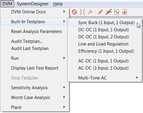 Result: The test selection dialog for the Sync Buck Testplan opens:
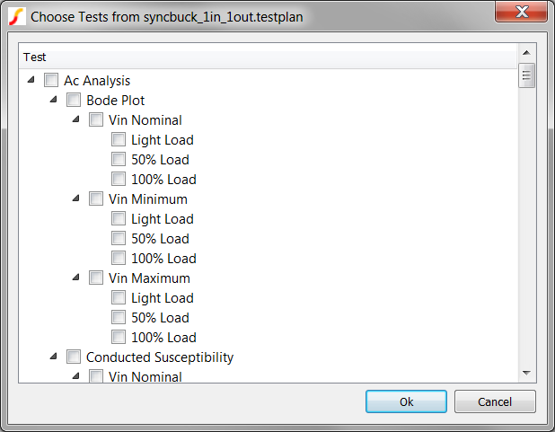
- Select three tests:
- Ac Analysis ▶ Bode Plot ▶ Vin Maximum ▶ 50% Load
- Transient ▶ Short Circuit ▶ Vin Maximum ▶ 100% Load to Short Circuit and Recover
- Steady-State ▶ Vin Maximum ▶ 50% Load
The dialog will look similar to the following:
Note: The two categories, Vin Nominal and Vin Minimum have been closed by clicking on the arrow symbol in front of the category to make the image smaller. You can also simply scroll down to see the tests.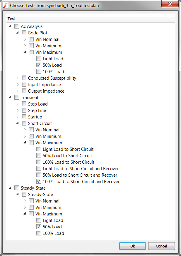
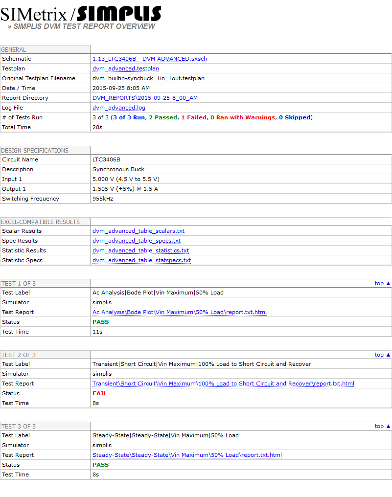
- Click Ok to run the selected tests. Result: DVM starts executing the three tests selected out of the built-in testplan. For each test:
- The circuit is configured prior to launching the SIMPLIS simulation.
- The simulation is executed.
- The graph results and scalar measurements are saved into the report directory.
Discussion
The Design Verification Module allows a user to setup and run multiple tests on a design in 5 minutes or less. The built-in testplans speed up the process by configuring the sources and loads as well as setting the analysis statements. DVM also makes scalar measurements and checks specification values to determine the pass/fail status of each test. Each built-in testplan covers a logical combination of input voltage and output load conditions, and is quite comprehensive. For example, the built-in testplan you just ran has 129 tests in total. On a reasonably powerful machine, a user can execute all 129 tests in this testplan in around 20 minutes on this model.
The only goal in this section is to make you aware that this kind of automation tool exists and is in use, perhaps by your customers. As a result, one of your customers could very easily convert your schematics to run in DVM and automate running simulations on the design.
What this Means:
- What takes a day by hand can be accomplished over a coffee break.
- The weaknesses of your model will be found out very quickly.
- If your model fails to converge in a POP analysis, you will hear about it. Or, SIMPLIS will hear about it, in either case, this reflects badly on both your company and SIMPLIS Technologies.
- If your model is really large, overly complicated, or for some other reason takes a long time to simulate, the user will know about it much earlier than you would expect.
Our leading customers tell us "This is what the future looks like."
These customers verify their designs with exhaustive simulation testing, especially where the cost of failure is very high. Their design verification test protocols include hundreds of simulations that must be analyzed and summarized. These design verification tests put a lot of strain on simulation models in terms of both accuracy and speed.
DVM provides a first level screen that demonstrates how well your model performs. If your model will successfully run the appropriate built-in testplan in a modest amount of time, it has passed the first test. If it took a day to complete, well, you have more work to do!
Tip of the Iceberg
The capabilities of DVM are much larger than the built-in testplans. Included in the examples zip file is an example titled 1.14_LTC3406B-CurrentLimit.sxsch. This schematic and the custom testplan generated for it: current_limit_1in_1out.testplan, which is in the testplans folder, explores the current limit behavior of the power supply. The testplan runs through a sequence of POP simulations where the output of the power supply is forced to a known voltage. Each test changes the output voltage, and after all tests complete, the average output voltage vs. average output current is plotted on a x-y graph. This is one of many advanced simulation scenarios which DVM can facilitate.
Conclusions and Key Points to Remember
- DVM allows rapid testing of a model over the gamut of operating conditions.
- Models which don't POP or require excessive simulation time will be a problem in DVM.
Reference Material: