Convergence
Simulations sometimes fail to converge - that is the simulation aborts before completion with one of these messages:
- No convergence in transient analysis
- No convergence in DC analysis
- Cannot find DC operating point - Iteration limit exceeded in pseudo transient analysis
- Cannot find DC operating point - No convergence in pseudo transient analysis
Convergence failures can be fixed by setting appropriate simulation options or by making changes to the circuit or by making changes to the models. Sometimes a combination of all three is required. See the following sections for more information:
In this topic:
Convergence Options
Select menu . You will be presented with this dialog box:
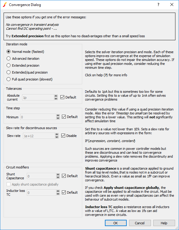
This dialog allows to set a number of simulation options that can help simulation convergence. These options sometimes have a penalty, either they slow down the simulation or in some way degrade accuracy. These are described below
| Item | Description |
| Iteration mode | Selects solver iteration and mode. Each of these options improves convergence at the expense of simulation speed. Extended precision mode provides a worthwhile convergence improvement with only a modest speed loss. |
| Tolerances | Setting current tolerance to 1n sometimes fixes convergence problems. You should not increase this setting if your circuit has very small currents |
| Time step | The Minimum Time step has a default value of 1e-18s. Lower values sometimes help transient analysis especially if using quad precision iteration modes. Increasing this value does not improve simulation speed. |
| Slew rate for discontinuous sources | This will only have an effect if you use models that contain discontinuous sources. These are common in switching power controllers |
| Shunt capacitance | This is often effective especially if the Apply shunt capacitance globally box is checked. However, this option is effectively modifying your circuit so should always be used with care. Note that this option will only benefit transient analysis |
Iteration Mode
The iteration mode trades off simulation speed with numerical noise. Numerical noise is one of the major causes of simulation failure in transient analysis. Numerical noise is the noise induced as a result of uncertainly in a calculation due to the limited precision of the arithmetic and is sometimes referred to as round-off error. It is similar in concept to quantization noise that is prevalent in data converters. Numerical noise increases as the time step reduces due to the behaviour of reactive components and can reach levels that exceed the tolerance parameters that determine when convergence has been reached.
SIMetrix provides a range of iteration modes that reduce numerical noise by employing a higher precision in its numerical calculations. In addition SIMetrix offers an advanced iteration mode which lowers numerical noise by employing a more efficient iterative equation.
| Mode | Typical numerical | Typical simulation | Advanced | Precision |
| Normal | 1 x | 1x | No | Double/Extended |
| Advanced iteration | ???MATH???\div???MATH??? 100 | + 5% | Yes | Double/Extended |
| Extended precision | ???MATH???\div???MATH??? 10000 | + 10%-30% | Yes | Extended |
| Extended/quad precision | ???MATH???\div???MATH??? 1e18 | 2x to 8x | Yes | Extended/Quad |
| Quad precision | ???MATH???\div???MATH??? 1e18 | 4x to 10x | Yes | Quad |
Double precision has a decimal resolution of approximately 16 digits. Extended precision has a decimal resolution of approximately 19 digits. Quad precision has a decimal resolution of approximately 34 digits
Convergence Failure Report
The convergence failure report provides details of items that caused the convergence failure. To create a convergence report, select menu . The report is divided into the following sections:
| Nodes which failed to converge on the final step | Lists circuit nodes whose failure to converge led to the simulation aborting. These should usually be the initial focus for investigation. These nodes will be highlighted on the schematic if at the top level of the hierarchy and this often shows the general area that is giving trouble |
| Devices which failed to converge on the final step | Devices whose failure to converge led to the simulation aborting |
| Items which failed to converge earlier in the run | The items listed here did not necessarily lead to the failure. However, devices or nodes that often fail during a run may be worth investigating. The Count value indicates how often the item failed. |
| Nodes which overflowed during the run | If a node voltage exceeds a preset limit, the iteration is aborted and then repeated with a smaller step. This is not necessarily a cause for concern but if the same node frequently overflows, this could be indicative of some problem |
| Static audit of circuit | Result of a static analysis of the circuit. See below for further details |
Convergence Static Analysis
The convergence static analysis feature performs an analysis of the circuit to identify items that can give trouble and could lead to convergence failure. The static analysis is automatically performed as part of the convergence failure report but may also be run on its own before or after a simulation using the menu . If run before a simulation, a dummy run of the simulation will be required and you will be prompted whether you would like this to be performed. This will load the circuit into the simulator but not actually start the run.
The static analysis will identify the following potential problems:
| Code | Description |
| IfDiscontinuity | Arbitrary source expression in the form IF(expression, constant, constant). These are discontinuous as they switch abruptly from one value to another with no time definition. This can lead to convergence failure |
| SgnDiscontinuity | Use of Sgn (sign) function in an arbitrary source. These can be discontinuous although it depends on how they are used. If this is reported in an Infineon MOSFET or IGBT model then it can be safely ignored |
| StpDiscontinuity | Use of U() or Stp() functions in an arbitrary source. Can be discontinuous but depends on how they are used |
| FloorDiscontinuity | Use of floor function in an arbitrary source. This is discontinuous and often gives convergence problems |
| DivideByZero | A divide by zero condition was detected in an arbitrary source |
| DivideByVar | This means something of the form expression/V(n1) or expression/(V(n1,n2) or expression/(V(n1)-V(n2)) or expression/I(v). In each case the V() or I() access function can - and usually does - return zero at some point leading to a divide-by-zero error |
| ValueTooSmall | A model or device parameter was set to a value that is too small. An example is the N parameter for a diode model. Small values are often used in models in order to make a diode with a small voltage drop but this can lead to difficulty in some situations. |
| ValueTooLarge | A model or device parameter was set to a value that is too small. Large capacitors trigger this failure for example |
| ◄ DC Sensitivity | Data Handling and Keeps ▶ |