Analysis Modes
In this topic:
Overview
In this section we explain how to setup the most commonly used analysis modes in both SIMetrix and SIMPLIS (SIMetrix/SIMPLIS product only)
For more comprehensive details on analysis modes, see Analysis Modes for SIMetrix and SIMPLIS Analysis Modes for SIMPLIS .
Setting up a SIMetrix Simulaton
Analysis mode is setup by selecting the menu . In SIMetrix mode this displays the following dialog box:
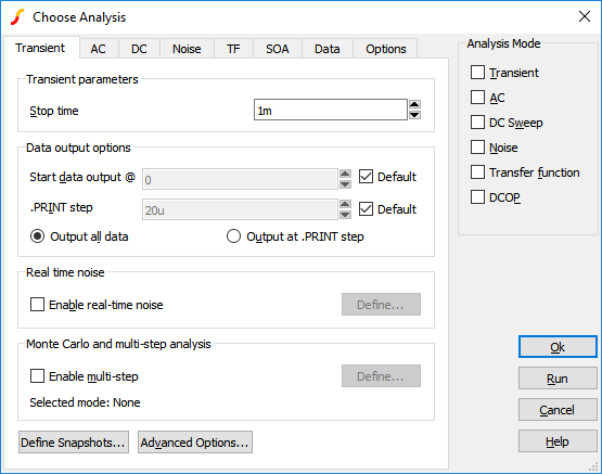 To set up the analysis, first check the box on the right according to which analysis you wish to perform. You can select more than one, but usually it is easier to do just one at a time.
The following describes the most commonly used modes and how to set one up.
Transient
The most useful and general mode. First the bias point is found. Then the circuit is simulated over a fixed time interval in steps of varying size according to circuit activity. The circuit may contain any number of time varying voltage and current sources (stimuli see Circuit Stimulus) to simulate external signals, test generators etc.
Usually you only need to specify the Stop time specified at the top of the dialog box. For information on the remaining options see Transient Analysis.
DC Device Sweep
A DC device sweep will sweep a specified device over a defined range and compute the DC operating point of the circuit at each point. This allows, for example, the DC transfer function of the circuit to be plotted. Note that all reactive elements are ignored in DC sweep.
To set up a DC Sweep, select the DC Sweep check box at the right and the DC tab at the top. You will need to enter some values in the Sweep Parameters section:
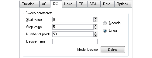
The analysis will sweep the device you specify in the Device name box over the range specified by Start value, Stop value and Number of points or Points per decade if you select a decade sweep.
The entry in the Device name box is the part reference of the device to be swept and for DC sweep would usually be a voltage source, a current source or a resistor.
Device sweep is just 1 of 5 modes available with DC sweep. The Define... button allows you to specify one of the others. See DC Sweep for details.
AC Frequency Sweep
An AC Frequency Sweep calculates the small signal response of a circuit to any number of user defined inputs over a specified frequency range. The small signal response is computed by treating the circuit as linear about its DC operating point.
There must be at least one input source for AC analysis for the results to be meaningful. Connect a voltage or current source to the circuit, select it then press F7. In the dialog box select the Enable AC check box. On the circuit, an AC input voltage source will look something like this:

To set up an AC Frequency Sweep, select the AC check box at the right and the AC tab at the top. You will need to enter some values in the Sweep Parameters section:
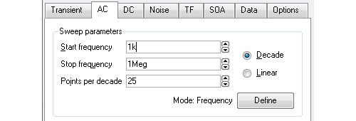
The analysis will sweep the frequency over the range specified by Start frequency, Stop frequency and Number of points or Points per decade if you select a decade sweep.
Frequency sweep is just 1 of 6 modes available with AC sweep. The Define... button allows you to specify one of the others. See AC Sweep for details.
Noise Frequency Sweep
Like AC analysis, Noise analysis is a small signal mode. Over a user defined frequency range, the circuit is treated as linear about its DC operating point and the contribution of all noisy devices to a designated output is computed. The total noise at that output is also calculated and optionally the noise referred back to an input source may also be computed.
To set up a Noise Frequency Sweep, select the Noise check box at the right and the Noise tab at the top. You will need to enter some values in the Sweep Parameters section:
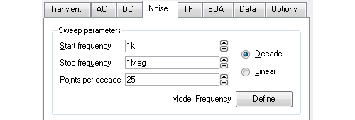
The analysis will sweep the frequency over the range specified by Start frequency, Stop frequency and Number of points or Points per decade if you select a decade sweep.
You will also need to enter some additional parameters:
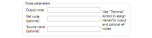 An entry in the Output node box is compulsory. It is the name of the circuit node as it appears in the netlist. Usually the schematic's netlist generator chooses the node names but we recommend that when running a noise analysis that you assign a user defined name to your designated output node. You can do this using a terminal symbol () To find out more see Finding and Specifying Net Names.
An entry in the Ref node box is optional. It is the node to which the output node is referenced. If omitted it is assumed to be ground.
An entry in the Source name box is optional. If specified the noise referred back to it will be calculated. Enter the part reference of the voltage or current source that is used as the input to your circuit.
Frequency sweep is just 1 of 6 modes available with Noise Analysis. The Define... button allows you to specify one of the others. See Noise Analysis for details.
DC Operating Point
To specify a DC operating point analysis, check the DCOP box on the right of the Choose Analysis Dialog.
Note that the DC operating point is calculated automatically for all the other analysis modes described above although for noise analysis the results are not stored.
After a DC operating point has been completed, you can annotate your schematic with markers to display the voltages at each node. Press ctrl-M on the schematic to place a single marker or select the popup menu to automatically place markers on all nodes. See Viewing DC Operating Point Results for full details.
Other Analysis Modes
| Real-time noise | An extension of transient analysis which enables noise generators for noisy devices using the same equations used for small signal noise analysis. See Real Time Noise. |
| Transfer function | Similar to AC but instead of calculating the response to a (usually) single input, it calculates the response from all signal sources to a single output. See Transfer Function. |
| Sensitivity | Calculates the sensitivity of a specified output to device and model parameters. See Sensitivity. |
| Multi-step Analyses | Transient, AC, DC, Noise and Transfer Function analyses can be run in an auto-repeat mode while stepping a user-defined parameter. See Multi-step Analyses. |
| Monte Carlo Analysis | See Monte Carlo Analysis. |
Setting up a SIMPLIS Simulation
SIMPLIS analyses are setup using the same menu as SIMetrix but you must first set the schematic to SIMPLIS mode. See Simulation Modes - SIMetrix or SIMPLIS for details.
Select menu . You will see the following dialog box:
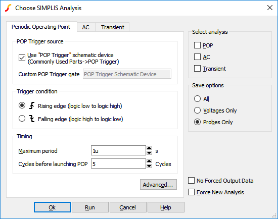 SIMPLIS has three analysis modes, namely Transient, Periodic Operating Point (POP) and AC. Transient is similar to SIMetrix transient analysis. POP is a unique analysis mode that finds the steady state of a switching circuit. AC finds the small signal response of a periodic system.
Transient Analysis
To setup a basic transient analysis:
-
Click on the Transient tab:
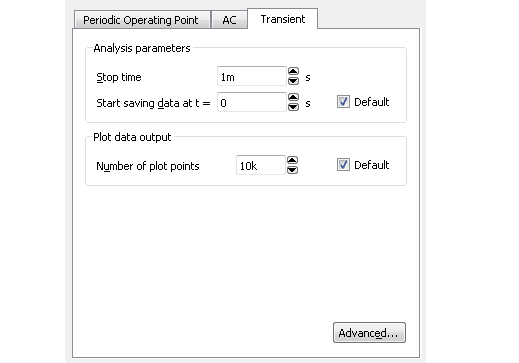
- Check the Transient box in the Select analysis section.
- Enter an appropriate stop time under Analysis parameters.
- Enter an appropriate selection under Save Options. Its usually best to select All. This will instruct SIMPLIS to save all data for subsequent plotting.
Periodic Operating Point Analysis (POP)
-
Select Periodic Operating Point sheet:
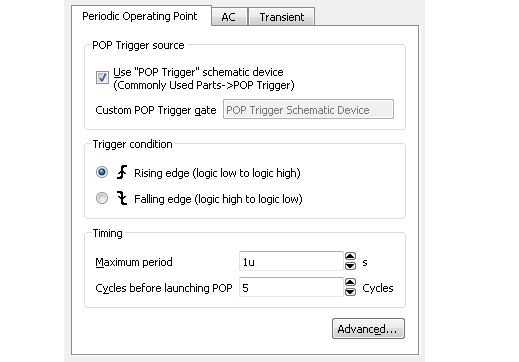
- Check the POP box under Select analysis.
- Check the Use "POP Trigger" schematic sevice box. You will need to place a POP trigger device on your schematic. See below.
- In the Maximum period box, enter a value that is larger than the largest possible value of your circuits switching period.
AC Analysis
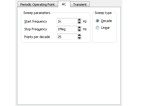
To setup an AC analysis:
- Select AC sheet.
- Check the AC box under Select analysis.
- Enter parameters in Sweep Parameters section. These have the same meaning as the equivalent SIMetrix analysis.
Manual Entry of Simulator Commands
The analysis mode selected using is stored in text form in the schematic's simulator command window also known as the F11 window. If you wish, it is possible to edit this directly. Users familiar with the simulator's syntax may prefer this approach. Note that the text entered in the simulator command window and the Choose Analysis dialog box settings remain synchronised so you can freely switch between the two methods.
To open the simulator command window, select the schematic then press the F11 key. It has a toggle action, pressing it again will hide it. If you have already selected an analysis mode using the Choose Analysis dialog box, you will see the simulator controls already present.
The window has a popup menu selected with the right key. The last item - Edit file at cursor - will open a text editor window with the file name pointed to by the cursor or selected text item if there is one.
The simulator command window can be resized using the splitter bar between it and the schematic drawing area.
If you have SIMetrix/SIMPLIS you should use the .SIMULATOR control to mark SIMetrix and SIMPLIS entries. If .SIMULATOR SIMetrix is encountered, all following lines will only work in SIMetrix mode and will be ignored by SIMPLIS. Conversely, any lines following .SIMULATOR SIMPLIS will only be accepted by SIMPLIS and will be ignored by SIMetrix. All lines before any occurrence of .SIMULATOR or after .SIMULATOR DEFAULT will be accepted by both simulators.
| ◄ Circuit Rules | Running the Simulator ▶ |