4.3 Load a Different Transformer Design
In this section, you will simulate a different transformer design with lower core losses. However, you will not design it yourself as in the previous sections, but will load a prepared design from a file.
In this topic:
Key Concepts
This topic addresses the following key concepts:
- MDM inductor and transformer models (designs) can be saved to a SIMPLIS MDM Geometry Design File (*.gmd).
- Instead of designing an inductor or transformer from scratch each time, or saving different versions of schematics for each different MDM physical model you create, you can load different MDM models (designs) into the same schematic by loading from a SIMPLIS MDM Geometry Design File (*.gmd) in the MDM main window.
- You can easily re-use the same inductor or transformer design in different schematics. It is of course up to you to make sure that using a particular transformer or inductor inside a given schematic makes sense.
What You Will Learn
In this topic, you will learn the following:
- How to save an MDM model to a .gmd file.
- How to load an MDM model from a .gmd file.
4.3.1 SIMPLIS MDM Geometry Design File
When you click Finish after creating an inductor or transformer design, a physical model of this inductor and transformer is stored by MDM in memory. However, when you shut down SIMetrix/SIMPLIS, this memory is of course cleared. To allow that physical model in MDM to be regenerated next time you start and open that same schematic, MDM generates a SIMPLIS MDM Geometry Design File that describes your design. After you click Finish, this file is not saved to disk. Rather, its contents - and XML string describing your design - are added as a symbol property to the inductor or transformer symbol you created and MDM model for.
To view the file for the design you last created in the previous section,
- Right-click the symbol TXResult: The context menu for the Multi-Level Lossy Transformer shows up.
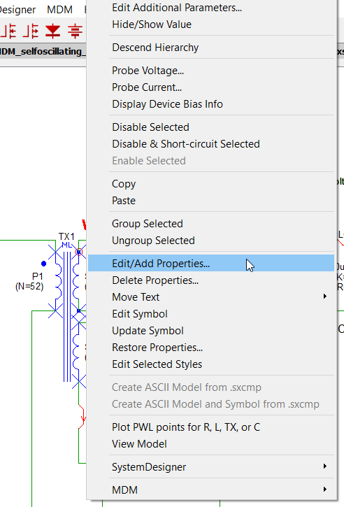
- Click the Edit/Add Properties.Result: The Edit Properties dialog appears:
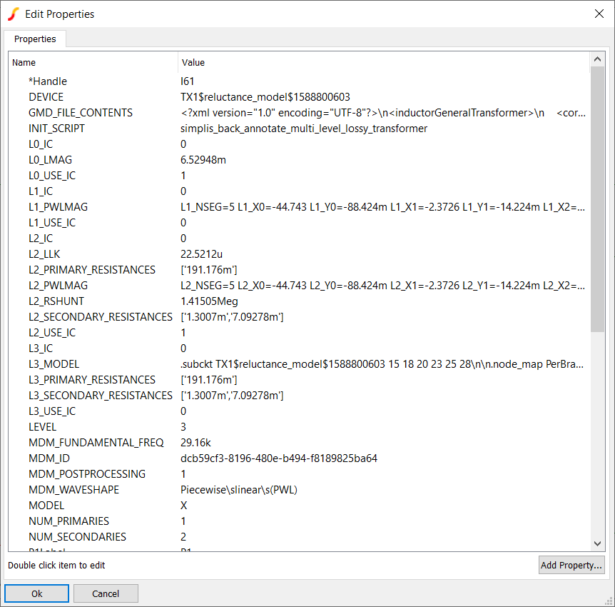
- Double-click the property GMD_FILE_CONTENTS.Result: The Edit Property dialog appears:
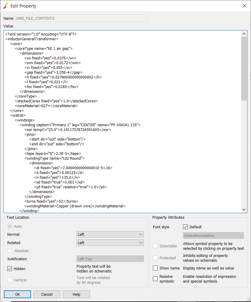
Now you can see the contents of the geometry design file. When you close and then re-open SIMetrix/SIMPLIS, and open this schematic and run the simulation or click to edit the design in MDM, this information will be passed to MDM and it will regenerate from it the physical model of the transformer in memory. However, this information is attached here only to the particular symbol you created it for, in this case TX. If you open the design in MDM, and change it, a new geometry design file will be created, overwriting the old one, and the old design will be lost. To avoid losing the old design, you would need to first save a copy of the entire schematic with this old design, and then save the version with the new design to a separate schematic file. This is what you have been doing so far in this tutorial. Often, as in this tutorial, you will be changing the transformer and inductor design MDM without changing the rest of the schematic. Therefore saving a new schematic for each new design in MDM is inefficient. There is a better way to save your MDM designs for future use.
Click Cancel twice to close all of the dialogs.
4.3.2 Save an MDM Design to a File
You can save a SIMPLIS Geometry Design File to disk, to an actual file with extension .gmd. To do this,
- Double-click the symbol TX1.
- Click the Edit with SIMPLIS MDM... button.
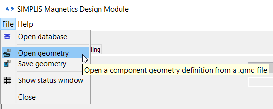
- In MDM main window, from the menu bar, select File > Save geometry:
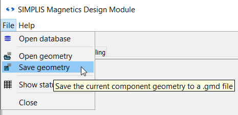
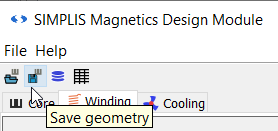
- Alternatively, click the second button in the task bar:
- The Save Geometry dialog shows up:
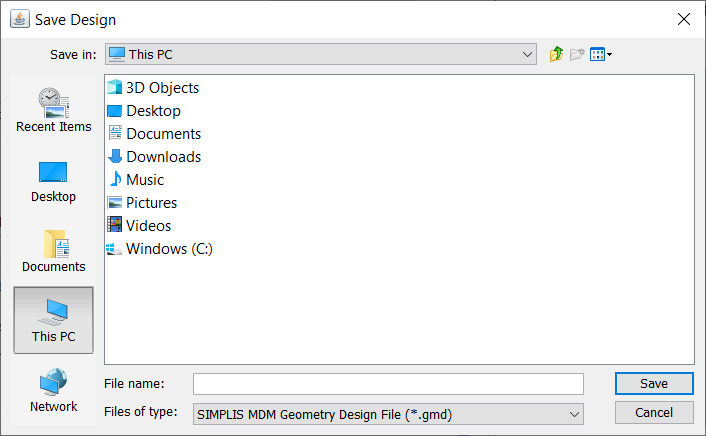
- Navigate to the directory where you previously saved the schematic files for this tutorial.
- Enter my_trans_design.gmd as the File name and click Save.
You have now saved your design to a .gmd file on disk and can re-load it later into this schematic, or another one.
All of the designs you created previously during this tutorial have been provided to you in the zip archive of schematic files:
- 2.3_inductorE30.gmd for the inductor design in section 2.3 Design an Inductor Using MDM
- 2.4_inductorRM4.gmd for the inductor design in section 2.4 Refine the Inductor Design Using MDM
- 2.5_inductorRM4_heatsink.gmd for the inductor design in section 2.5 Change the Cooling Parameters in MDM
- 4.2_transformerE55_solidwire.gmd for the initial transformer design in section 4.2 Design a Transformer in SIMPLIS MDM
- 4.2_transformerE55_tape_litzwire.gmd for refined transformer design in section 4.2 Design a Transformer in SIMPLIS MDM
4.3.3 Load an MDM Design from a File
Now load a new transformer design, that has already been prepared for you, from file:
- In MDM main window, from the menu bar, select File > Open geometry:
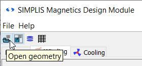
- Alternatively, click the first button in the task bar:
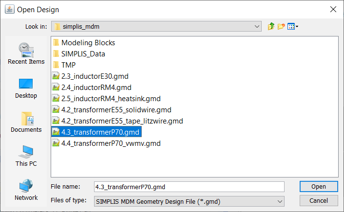
- The Open Design dialog shows up. Navigate to the directory where you extracted the zip archive of schematic files, and select the file 4.3_transformerP70.gmd:
A new design is now loaded into the MDM main window:
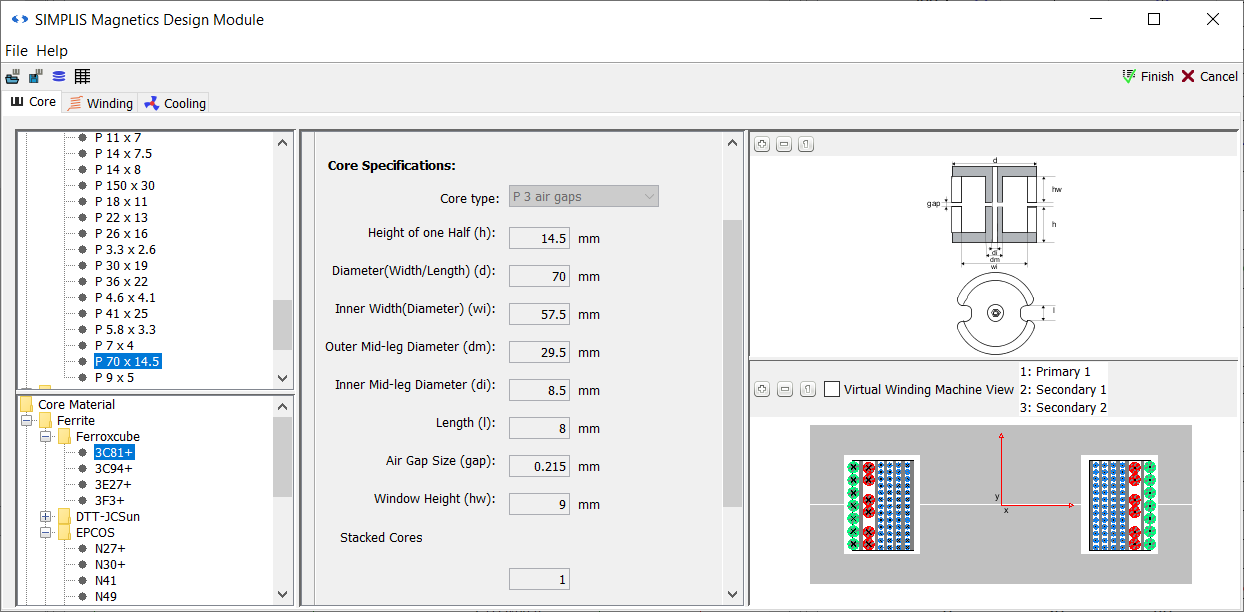
You can see that this design uses both a different core material - Ferroxcube 3C81+ - and different core. A three-gap pot core, P 70 x 14.5, is used, where the air gap on each core leg has been set to 0.215mm. If you look at the Status Window, you will see that this transformer has a magnetizing inductance of 6.6073mH.
Now switch to the Winding tab:
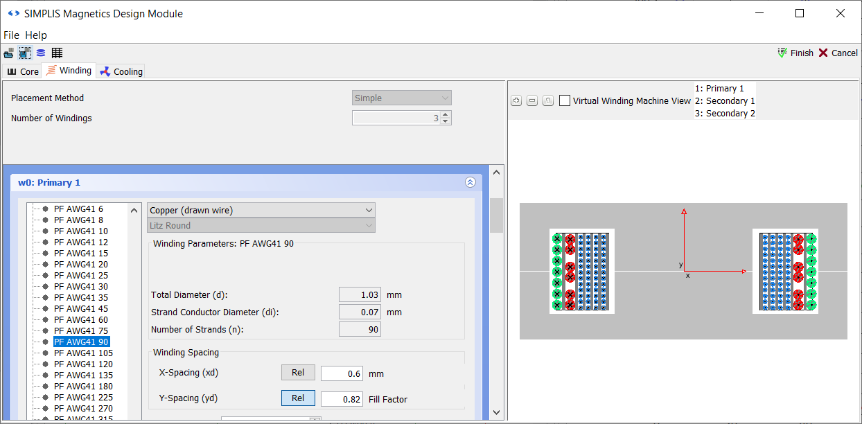
All the windings and layers in this design are separate by 0.6mm of tape. All the turns are spread out evenly along the bobbin. All windings use litz wire: Primary 1 uses single-filar PF AWG41 90, Secondary 1 is wound from double-filar PF AWG41 405 wire, and Secondary 2 from single-filar PF AWG41 405 wire.
4.3.4 Simulate the Loaded Design
Click Finish to save the loaded design to the schematic.
.Save the schematic as 4_myflyback_transformer3.sxch. A complete schematic with the inductor design developed in this sub-section, set up for MDM post-processing, is available as 4.2_SIMPLIS_MDM_selfoscillating_flyback_converter_with_loaded_transformer_design.sxsch in the zip archive of schematic files.
Press F9 to run the simulation. A new MDM Results Window will appear. However, if you look at the Waveform Viewer, you will notice that now, due to different transformer design, the switching frequency has increased to 29.83kHz:
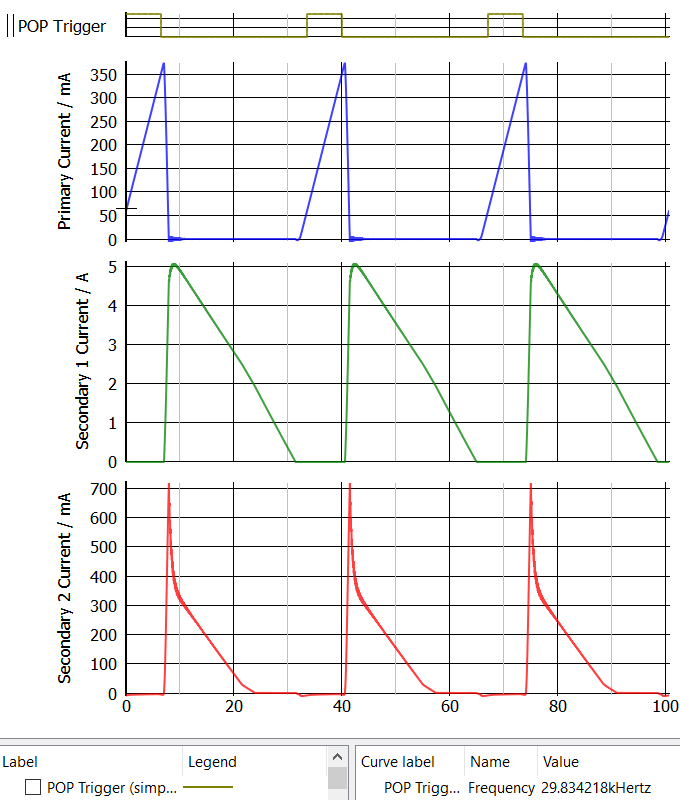
Therefore you must adjust the fundamental frequency for MDM post-processing to get valid results:
- Close the MDM Results Window that just appeared. The results there are calculated using the wrong fundamental frequency and should be discarded.
- Double-click the symbol TX1.
- For Fundamental frequency, enter 29.83k.
- Click OK.
- Save the schematic.
- Press F9 to re-run the simulation.
Result: A new Results Window appears, with the correct loss calculation:
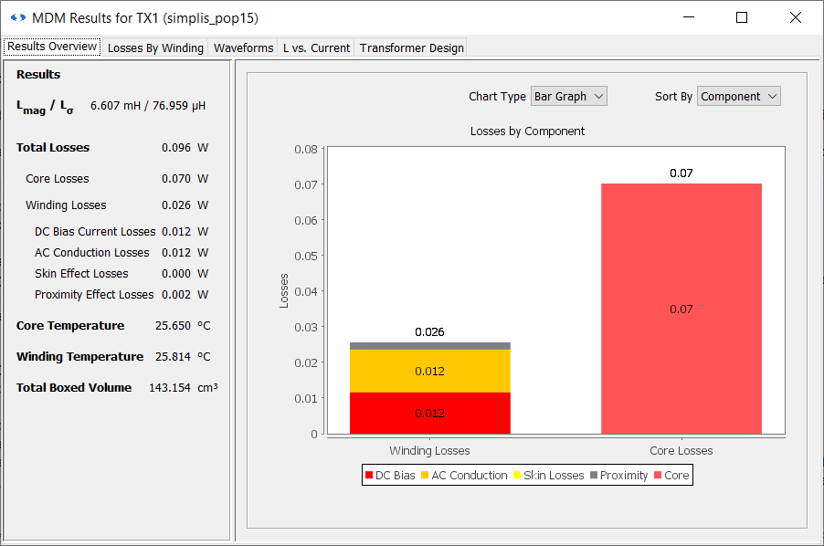
Compared to your refined design from the previous section, the core losses have been reduced quite signficantly - more than ten times - to 70mW. However this core is much larger then the E55 core used previously, giving a boxed volume of 143.154cm3, more than double the designs from the previous section. This is on part of the explanation the lower core losses - a larger core results in a significantly lower peak flux density for the same winding currents. The rest of the difference is explained by the fact that the 3C81+ material has lower core losses at this operating point than the previously used N27+ material.
Proximity losses are low at 2mW due to the use of litz wire, being reduced compared to the previous design by half, but total winding losses are actually quite higher at 26mW. The larger core necessitates a longer length of wire for the same number of turns, thereby causing higher conduction losses. However since the core losses are low, the total transformer loss is only 96mW, a reduction of almost 90% compared to the refined design in the previous section.
On the other hand, the lekage inductance is significantly higher at 76.959μH. With this design, you have traded off a reduction in losses with an increase in volume and leakage.
You have now learned how to design a transformer using MDM, analyze the post-processing results, and refine and change your design. In the next and final section of this tutorial, you will see how MDM can help with figuring out how to wind your transformer.