Overview
In this topic:
Device Statement Format
The device statement defines how a device is connected in the circuit, and lists the values for the individual device parameters. If a device requires a device model or some initial condition, such information is also defined in the device statement. The format for a device statement is defined as follows:
DeviceName NodeName {Values|ModelName} [InitConds]
where
| DeviceName | is a legal device name |
| NodeName | is a sequence of legal node names |
| Values | is either a floating-point entry to stand for value or a sequence of parameter assignments |
| ModelName | is the legal name of a compatible model. The symbol {Values|ModelName} means Values and ModelName are mutually exclusive. If a device requires a model name, no Values would be given in the device statement and vice versa |
| InitConds | is a sequence of legal initial condition specifications. The symbol [InitConds] means the presence of the InitConds fields is optional since only some devices require initial conditions. |
Node Names
Each node in the circuit must be assigned a unique name. A legal node name is either a positive integer or zero. Remember that node 0 is traditionally reserved to represent the ground node. Also note that:
- SIMPLIS does not require the presence of node 0 in the system unless the user wants to inspect the voltage of a particular node with respect to a certain ground node
- SIMPLIS does not require every node in the system to be connected to each other, allowing the system to have isolated subsystem. However, error messages will be generated if the user instructs SIMPLIS to determine the voltage between two electrically isolated nodes.
Voltage and Current Polarity Conventions
Most of the circuit elements discussed in this chapter are two-terminal elements. For any general two-terminal element, there is a positive node n+ and a negative node n- as shown in the diagram below:
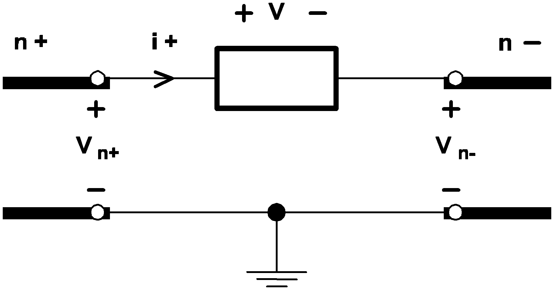 |
3.1 Definition of the voltage and the current association for a two-terminal element. |
V = Vn+ - Vn-as measured from the n+ terminal to the n- terminal.
When the current through a two-terminal device is mentioned in this manual, it refers to the current measured in the direction from the positive node through the element to the negative node. Thus, a positive current indicates that there is a net flow of charge into the positive node, through the two-terminal element, and then out of the negative node.
With these sign conventions for voltages and currents, a positive voltage-current product indicates that electric power is instantaneously flowing into the corresponding two-terminal element, whether it is a voltage or current source, a resistor, or any other two-terminal element.
Parameter Assignments
Parameters such as the initial conditions for devices are entered in a format called parameter assignments. The format is
KEYWORD=valuewhere
| KEYWORD | is the corresponding keyword representing the descriptive name of the parameter, |
| = | is the equal sign ('='), and |
| value | is the value assigned to the parameter. |
Controlling Devices
The four controlled sources, the simple transistor switch, and the simple switch are each controlled by a controlling variable that is external to the device. There are three types of controlling variables:
- A differential voltage across two nodes in the same circuit,
- A branch voltage across the positive and negative nodes of a controlling device in the same circuit, or
- A current through a controlling device in the same circuit.
- Linear resistors
- Linear inductors
- Linear capacitors
- All types of independent voltage sources
- All types of independent current sources
- All four types of linear controlled sources
- Simple transistor switches
- Simple switches
- Piecewise-linear resistors
- Piecewise-linear inductors
- Piecewise-linear capacitors
| ◄ Organization of the Input File | SIMPLIS Device Types ▶ |