Example 6 -- Saturable Inductor
Depending on the system design, a magnetic element may be intentionally or unintentionally driven into saturation during transient or during steady-state operation. This example illustrates the usage of piecewise-linear (PWL) inductors in the input file. The system under study is shown in fig. 9.17 (a), which comprises of a sinusoidal voltage source driving a resistor in series with a saturable inductor. Fig 9.17 (b) shows the piecewise-linear flux linkage versus current characteristic of the saturable inductor. The input file for this circuit is shown in 9.18.
The saturable inductor is modeled by the piecewise-linear inductor L1 (!L$L1 in the input file), with the flux linkage entered in units of weber-turns. The variables of interest are the input voltage V(VI), plus the voltage V(L1) and the current I(L1) of the PWL inductor. The simulated waveforms for these variables are shown in fig 9.19.
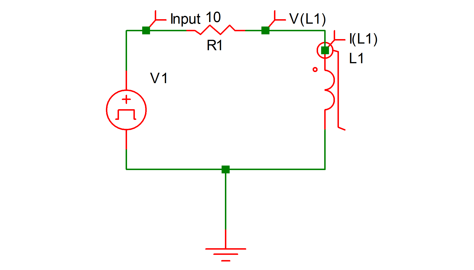 |
9.17a The circuit diagram |
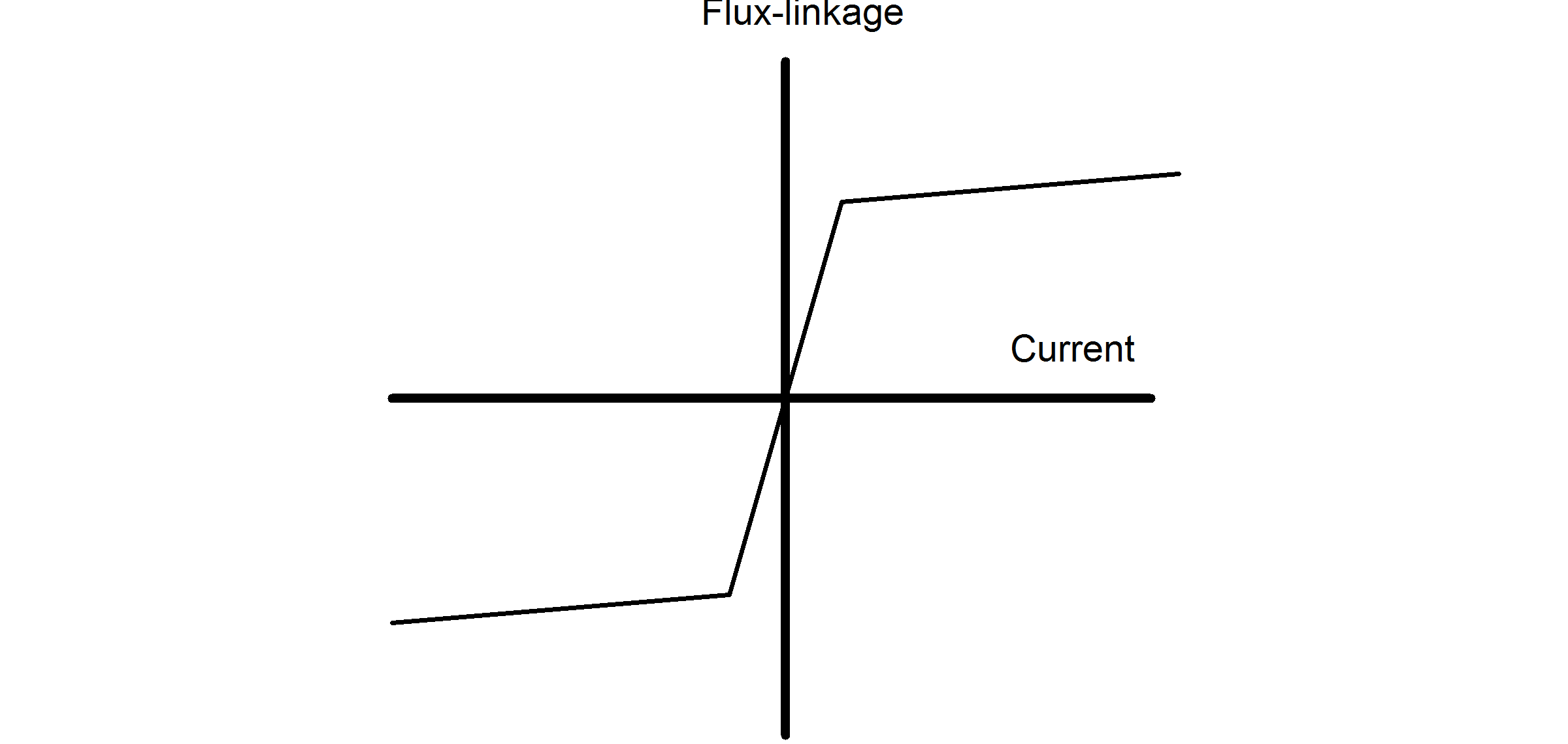 |
9.17b Flux-linkage vs. current characteristics of inductor |
* Cosine Wave Driving A Resistor And A Saturable Inductor

VI 1 0 COS VOFFSET=0 APEAK=75 FREQ=10K
.PRINT  ALL
.OPTIONS  PSP_NPT=201
.TRAN 200u 0
V1 1 0 COS VOFFSET=0 APEAK=75 FREQ=10k TDELAY=0
+ OFF_UNTIL_DELAY=NO DAMP_COEF=0
!L$L1 2 0 L1$TP_SSPWLL
.MODEL L1$TP_SSPWLL PWLL NSEG=3 X0=-0.1 Y0=-500.5U
+ X1=-0.05 Y1=-500U X2=0.05 Y2=500U X3=0.1 Y3=500.5U
R1 2 1 10
.END
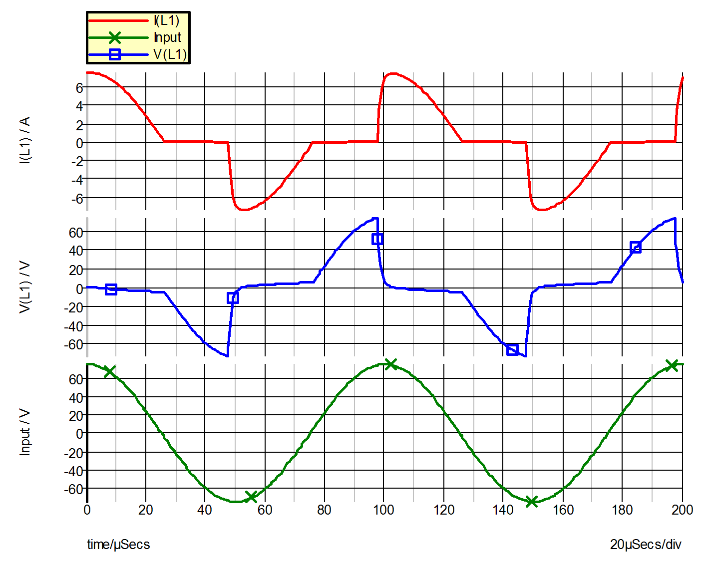 |
9.19 Waveforms for Example 6 |
| ◄ Example 5 -- Regulated Converter | Example 7 -- SCR with RL Load ▶ |