2.1 Add Symbols and Wires
This section of the tutorial describes how to start a design from a blank schematic.
In this topic:
Key Concepts
This topic addresses the following key concepts:
- The Commonly Used Parts category in the Part Selector contains all of the symbols for this schematic except the diode and the MOSFET.
- The SPICE models for discrete semiconductors, such as diodes and MOSFETs, are not directly used by SIMPLIS. Instead, a parameter extraction system uses SIMetrix to simulate the SPICE model and a set of curve-fitting algorithms generate a PWL model for use in SIMPLIS. This process happens before the symbol is placed on the schematic.
- Discrete semiconductors can be placed from the model library or by using keyboard shortcuts.
What You Will Learn
In this topic, you will learn the following:
- How to verify and change the simulator mode.
- Three ways to place symbols on a schematic:
- By using the Part Selector.
- By placing symbols from the model library.
- By using built-in keyboard shortcuts.
- How to wire symbols together to create a circuit.
- How to remove symbols and wires from a schematic.
Getting Started
Before proceeding you need to check the lower right corner of the main window to verify that SIMPLIS is the simulator mode.
- If the mode is SIMPLIS, proceed to section 2.1.1.
- If the mode is SIMetrix: from the menu bar, select to change the simulator mode to SIMPLIS.
2.1.1 Place the Symbols
This section demonstrates the three ways to place symbols on a schematic and is divided into two general steps:
- In Step One, you will add three symbols to illustrate the three ways to place symbols on a schematic.
- In Step Two, you will place the remaining symbols used in this design.
Step One: Place First Three Symbols
For this schematic, the Commonly Used Parts category in the Part Selector contains all the parts except the diode and the MOSFET; therefore, you will place the diode from the model library and then use a built-in keyboard shortcut to add the MOSFET.
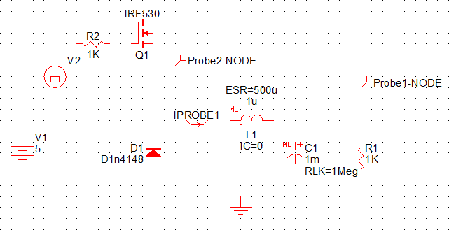
In this step, you will place the first three symbols, an inductor, a diode, and a MOSFET. Use the illustration below as a general guide to place the symbols on the schematic.
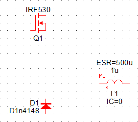
Inductor: To place the inductor (L1), follow these steps:
- From the Commonly Used Parts list, double click Multi-Level Lossy
Inductor (Version 8.0+). Result: The inductor appears on the screen.
- Move the mouse to where you want to place the symbol, and press the left mouse
button. Result: An inductor, with reference designator L1, is now in place.
Diode: To place the diode (D1) from the model library, follow these steps:
- In the Part Selector, double-click the Discretes category to expand the list.
- Double-click the Diodes category, and then click Select from Model
Library...
Result: The Select Device dialog opens.
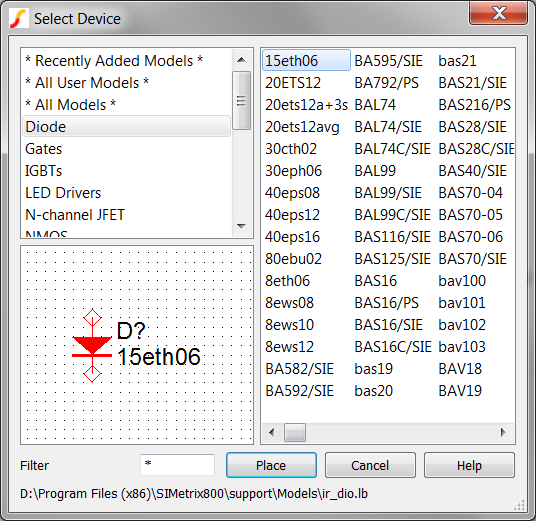
- In the Filter field at the bottom left side of the Select Device window,
put your cursor in front of the asterisk (*), and then type
D1n41.Result: D1n4148 appears as the only item available.
- Select D1n4148 in the top right pane, and then click the Place
button at the bottom of the Select Device window as shown below.
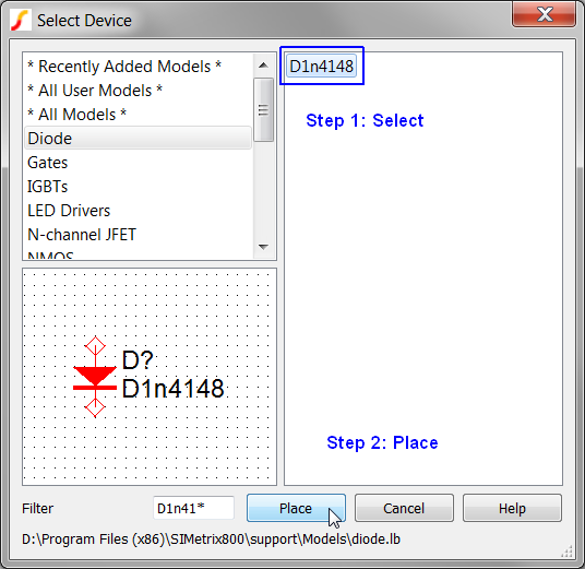 Result: The Extract Diode Parameters dialog opens.
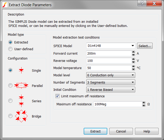
- Click Extract to accept the default values and close the dialog box.Result: Several SIMetrix SPICE simulations are run on the SPICE diode model and curve-fitting algorithms calculate a set of PWL parameters for use in SIMPLIS simulations.Note: Although a small-signal diode such as the D1n4148 is not appropriate for a synchronous rectifier application, you will change this diode model later in section 2.2 Edit Standard Component Values.
- Place the cross hair to the left and down from the inductor, and then press the
left mouse button. Result: A diode, with reference designator D1, is now in place.
- With the diode selected, press F5 two times to rotate the diode 180 degrees.
MOSFET: To place the MOSFET (Q1) using a keyboard shortcut, follow these steps:
- Move the mouse cursor directly above the diode, and type M. Note: The letter M is a keyboard shortcut which places a 3-terminal N-type MOSFET, as if you have navigated to the Select Device dialog as in Step 4.Result: The Extract MOSFET Parameters dialog opens.
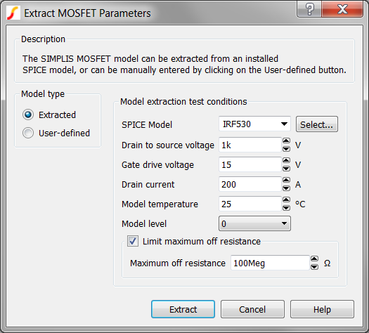
- Click Extract to accept the default values and close the dialog box. Result: As with the diode placed in the previous step, several SIMetrix SPICE simulations are run on the MOSFET model and curve-fitting algorithms calculate a set of PWL parameters for use in SIMPLIS simulations.Note: The original SPICE model is NOT used in the SIMPLIS simulations. As with the diode, you will change the part number for the MOSFET in section 2.2 Edit Standard Component Values.
- With the cross hair directly above the diode, click the left mouse button to
position the MOSFET symbol on the schematic. Result: A MOSFET with reference designator Q1 is now in place.
Step Two: Place Remaining Symbols
To place the remaining symbols, follow these steps:
- Place the symbols in the order listed in Table 1 below, using either of the
following methods:
- From the Part Selector Commonly Used Parts category, double click the part
name.
or
Type the keyboard shortcut if one is listed in the table.
- From the Part Selector Commonly Used Parts category, double click the part
name.
- Each time you place a symbol, move the mouse to the general location as indicated
on the diagram below, and then press the left mouse button to place the symbol on
the grid.
Label Commonly Used Parts Shortcut Comments C1 Multilevel Capacitor (Level 0-3 w/Quantity) (Version 8+) No keyboard shortcut R1 Resistor (Z Shaped) 4 V1 Power Supply v V2 Waveform Generator (Pulse, Ramp...) w . R2 Resistor (Z Shaped) 4 To rotate 270 degrees, press F5 three times. Ground g Probe1-NODE Probe-Voltage b Probe2-NODE Probe-Voltage b IPROBE1 Probe -Inline Current No keyboard shortcut Note: If you accidentally place an extra symbol, you can immediately remove it by typing Ctrl+Z or by selecting from the menu bar. If you did not remove the extra symbol immediately after placing it, see 2.1.3 Remove Extra Symbols and Wires.
2.1.2 Add the Wires
In this section, you will learn how to add connecting wires to a schematic.
To wire your symbols together, use the
diagram and steps below as a general guide: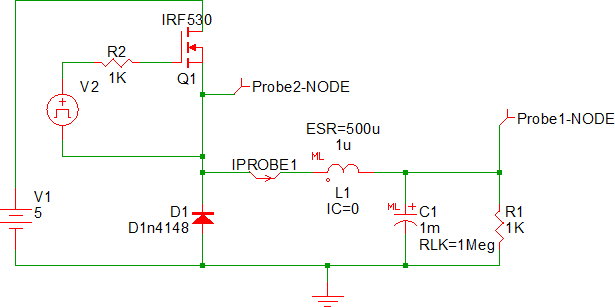
- Place the mouse pointer over a symbol pin. Result: The pointer changes to a pencil, indicating that the schematic is in wiring mode.
- To start a wiring segment, click the left mouse button.
- To create corner points, click the left mouse button again until you reach the symbol to which you are drawing a connection.
- When you finish drawing a segment, click the right mouse button or press
Esc.Note: If you accidentally place an extra wire, you can immediately remove it by typing Ctrl+Z.or by selecting from the menu bar. If you did not remove the extra wire immediately after placing it, see 2.1.3 Remove Extra Symbols and Wires.
2.1.3 Remove Extra Symbols and Wires
This section explains how to remove symbols and wires individually and in groups.
To remove an individual symbol or wire, follow these steps:
- Click on the symbol or wire that you want to remove. Result: The symbol or wire changes to blue, indicating that it is selected.
- Press the Delete key.
To remove a group of symbols and wires, follow these steps:
- To start a selection box, hold down the left mouse button while dragging the mouse to the opposite corner.
- When you have defined the area, release the mouse button. Result: The wires (and any symbols) inside the box change to blue, indicating these wires and components are selected.
- Press Delete. Result: The selected wires and components are deleted from the schematic.Note: To select extra wires and symbols. click anywhere on the schematic.
Special Case: Wires Inside a Symbol Boundary
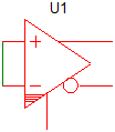
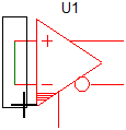
In some cases, you may want to remove wires that are inside the symbol bounds. The following example uses a comparator with the input pins shorted together as shown below. This procedure removes the wires, but leaves the symbol intact.
To remove only the wire segments, follow these steps:
- Press and hold the Shift key, click and hold the left mouse button as you
drag to select the wire area as shown below.
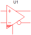
- When you have defined the area, release the mouse button. Result: The wires inside the box change to blue, indicating these wires are selected.
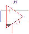
- Press Delete. Result: The selected wires are deleted from the schematic.
Special Case: Wires Which are Exactly One Grid Square Long
There are times when your schematic will have wires which are exactly one grid square long, and you would like to delete these wires. This is difficult because the program enters the wiring mode whenever the mouse cursor is within one-half grid square distance from a wire end. Here are a few solutions to this problem:
Disable the auto wiring by pressing and holding the Ctrl key when selecting the wire.
- Disable the auto wiring by pressing and holding the Ctrl
key when selecting the wire.
or
- Select the wire by dragging a box which encloses the wire.
Once the wires are selected, you can press the Delete key to remove them from the schematic.
2.1.4 Save your Schematic
To save your schematic, follow these steps:
- Select .
- Navigate to your working directory where you are saving your schematics.
- Name the file 1_my_buck_converter.sxsch.
A schematic saved at this state can be downloaded here: 1_SIMPLIS_tutorial_buck_converter.sxsch.