Multi-Level Lossy Transformer (Version 8.4+)
The Multi-Level Lossy Transformer has multiple levels of complexity for use in different simulation objectives. The transformer can have up to a total of 20 windings, and can be configured with varying levels of complexity:
- Level 0 : The level 0 transformer models a ideal transformer with linear magnetizing inductance. There are no winding resistances nor leakage inductance in this model.
- Level 1 : The level 1 transformer models a ideal transformer with piecewise linear magnetizing inductance. There are no winding resistances nor leakage inductance in this model.
- Level 2 : The level 2 transformer models a ideal transformer with piecewise linear magnetizing inductance. Leakage inductance for the transformer is referred to the first primary winding and DC winding resistances are included in the model.
- Level 3 : The level 3 transformer uses a full reluctance model created by the SIMPLIS Magnetic Design Module (MDM). MDM is a separately license feature for the SIMPLIS simulator. Without a MDM license, you will not see the radio button to select the Level 3 model.
Model parameters for each model level are independently stored on symbol properties dedicated to each model level. The model level parameter can then be changed to select which model is simulated.
In this topic:
| Model Name: | Multi-Level Lossy Transformer | |
| Simulator: | This device is compatible with the SIMPLIS simulator. | |
| Parts Selector Menu Location: | ||
| Symbol Library: | The symbol is automatically drawn when placed on the schematic. | |
| Model File: | simplis_param.lb (levels 0-2). The level 3 model is stored on the symbol as the L3_MODEL property. | |
| Subcircuit Name: | SIMPLIS_MULTI_LEVEL_LOSSY_TRANSFORMER (model levels 0-2). The subcircuit for the level 3 model is stored on the L3_MODEL property and the subcircuit name is unique. | |
| Symbol: | ||
| Multiple Selections: | Only one device at a time can be edited. | |
Editing the Multi-Level Lossy Transformer
Windings
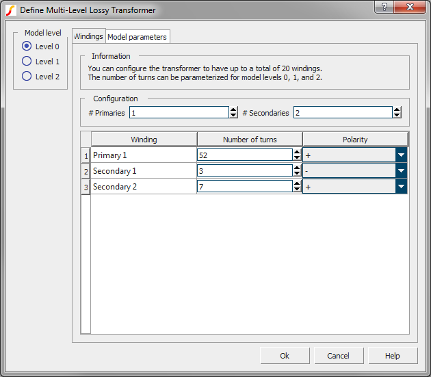
The parameters on the windings tab define the number of primary and secondary windings, the number of turns for each winding, and the "dot" polarity of each winding. You can edit the winding names on this tab, and the winding names will be copied to the Parameters tab on the dialog. For model levels 0-2, the number of turns on the dialog can be parametrized. For the level 3 model, the number of turns must be an integer value - no parameterization is allowed. The transformer symbol is re-drawn after you accept the dialog using the number of primary and secondary windings. For this reason, the number of primary and number of secondary windings cannot be parametrized.
Level 0 Transformer Parameters
| Parameters | Units | Description |
| Magnetizing inductance (LMAG) | H | The magnetizing inductance in Henries. |
| Use IC? | n/a | If checked, the model will use the Initial condition parameter to initialize the magnetizing inductance. |
| Initial condition | A | The initial current at t=0 in the magnetizing inductance. |
Level 1 Transformer Parameters
| Parameters | Units | Description |
| Piecewise linear magnetizing inductance (LMAG) | n/a | Clicking on the Define... button opens a PWL table editor dialog where you can define the PWL characteristics of the magnetizing inductance. The initial conditions are also defined on this sub-dialog. |
Level 2 Transformer Parameters
| Parameters | Units | Description |
| Piecewise linear magnetizing inductance (LMAG) | n/a | Clicking on the Define... button opens a PWL table editor dialog where you can define the PWL characteristics of the magnetizing inductance. The initial conditions are also defined on this sub-dialog. |
| Leakage inductance | H | The leakage inductance of the transformer referred to the first primary winding. |
| Shunt resistance (RSHUNT) | Ω | The shunt resistance across the leakage inductance. The shunt resistance limits the high frequency behavior of the leakage inductance. Click the Calc... button to calculate the shunt resistance based on the leakage inductance value and the desired highest frequency. |
Level 3 Transformer Model
The level 3 transformer model is created by the SIMPLIS Magnetic Design Module (MDM) and the subcircuit model is stored on the transformer symbol property L3_MODEL. The electrical model is a complete reluctance circuit where the effective magnetizing inductance is piecewise linear, and the leakage inductance is modeled for each winding.