Basic DVM Control Symbol
The Basic DVM control symbol holds the minimum amount of information that is required to run DVM. The Full Power Assist DVM Control Symbol stores additional information, such as specifications for the sources and loads, as well as performance specifications. The DVM control symbol dialog consists of two areas:
- The page selection box on the left where you select the page that you want to edit
- The entry fields on the right side of the dialog where you enter the specifications
Adding a Basic DVM Control Symbol to a Schematic
To add a Basic DVM control symbol to a working schematic, follow these steps:
- From the parts selector, choose DVM ▶ Control Symbols ▶ Basic DVM Control
Symbol. Result: The DVM Basic Control Symbol appears.
- Place the symbol on the schematic.
- Double click the symbol. Result: The SIMPLIS DVM Control Panel dialog opens for you to enter the information that is described in the following sections.
Circuit Specifications
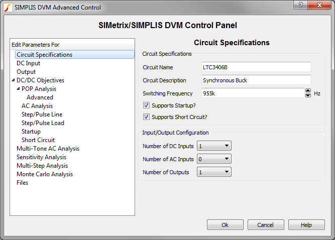
The Circuit Specifications page allows you to define circuit descriptions and specifications that DVM uses when measuring and checking scalar values in the simulation. On this dialog, you also specify the number of DC inputs, AC inputs, and outputs. Additional pages appear for each input and for each output as shown in the page selection panel below. This dialog is configured for one DC input and one output load.
| Label | Parameter Description |
| Circuit Name | Name of the circuit as it will appear in the DVM report; for display purposes only. |
| Circuit Description | Description of the circuit under test which appears in the DVM Control symbol; for display purposes only. |
| Switching Frequency | Nominal switching frequency used to calculate simulation timing for DC/DC test objectives |
| Supports Startup? | If checked, the Startup() test objectives startup tests will be performed; if not checked, the Startup() test objectives will be skipped. |
| Supports Short Circuit? | If checked, the ShortCkt() test objectives will be performed; if not checked, theShortCkt() test objectives will be skipped. |
| Number of DC Inputs | The numbers that you select in these three fields dynamically change the page selection list to accommodate the number of AC and DC inputs and the outputs that will then be available for you to configure. |
| Number of AC Inputs | |
| Number of Outputs |
Multi-Step Analysis
The DVM Multi-Step Analysis allows you to step a set of design parameters over a range of values using a decade-step or linear-step sequence. You may also step values over a defined list of parameter values. One advantage of using a single test with a multi-step analysis over multiple DVM tests is the multi-core capability which is part of the Pro and Elite license packages. The multi-core capability runs steps in parallel on multiple processor cores and will greatly reduce the simulation time required for the multi-step analysis. Even using a single processor core reduces the required simulation time as the schematic is setup once, as is the graph and data collection after the simulation completes.
For more information, see the Multi-Step Analysis topic.
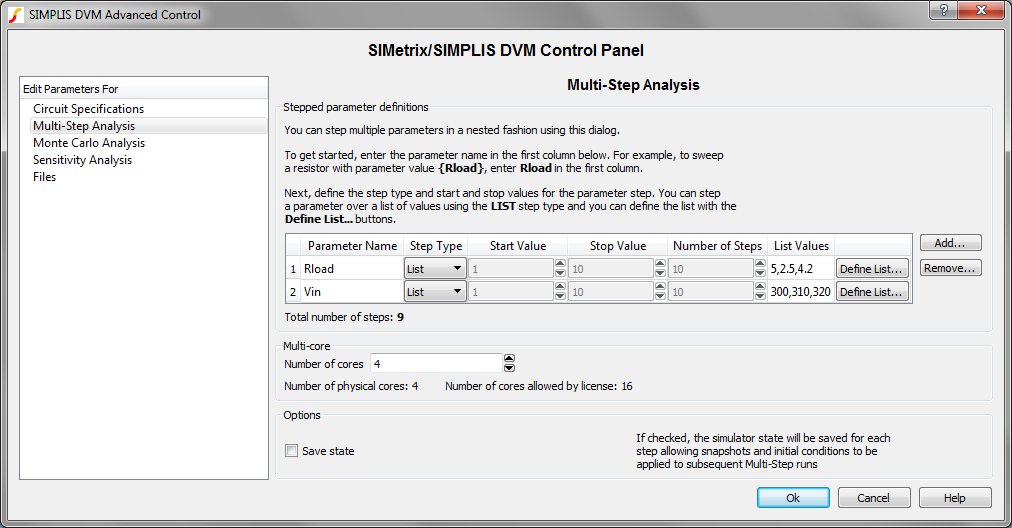
The table on the Multi-Step Analysis page allows you to enter the parameter names and their associated step parameters. The dialog allows you to configure three different step modes:
- A Linear step where the parameter is stepped from the Start Value to the Stop Value using the Number of Steps in a linearly spaced sequence. The number of steps run will always be the parameter entered into the Number of Steps field.
- A Decade step where the parameter is stepped from the Start Value to the Stop Value using the Number of Steps per decade in a logarithmic sequence. The total number of steps depends on the Start Value, Stop Value, and the Number of Steps.
- A List sequence where the parameter is stepped over a user-defined list of parameter values. There are no restrictions on the values of the list. The total number of steps depends only on the number of values entered.
To enter parameter step information, follow these steps:
- Enter a parameter name in the Parameter Name column.
- Select the desired Step Type from the drop-down list. After you select the step type, the rest of the valid controls for this parameter are enabled.
- For List step types, enter the list of values by double clicking on the List Values table cell or click on the Define List... button.
| Table Column | Description |
| Parameter Name | The name of the stepped
parameter. The schematic symbols should be parameterized with this
parameter name using braced {} substitutions as shown at the top of the
dialog image above. Note: You can automatically change symbol property
values by using the Change testplan entry.
|
| Step Type | The step type can be one of
the following:
|
| Start Value | The starting value for the parameter step, used with decade and linear steps |
| Stop Value | The ending value for the parameter step, used with decade and linear steps |
| Number of Steps | The number of steps for the decade or linear steps. For decade steps, this parameter value is the number of steps per decade, for linear steps, the parameter value is the number of equally spaced steps. |
| List Values | The list of stepped values. This cell is automatically populated by the dialog opened with the Define List... button. |
Additional parameters can be stepped by clicking on the Add... button and individual parameters can be removed with the Remove... button. The total number of steps is the product of number of steps for each stepped parameter. The total number of steps is calculated and shown below the table in the Total number of steps text.
| Multi-core | |
| Number of cores | The number of cores used for the simulation. The Pro and Elite licenses allow the use of 4 and 16 cores respectively. |
| Save state | If checked, SIMPLIS will save initial conditions files with names which reflect the stepped parameter values. You can use the GenerateInitFile entry to save the initial conditions files and the IncludeInitFile entry to include these files. |
Monte Carlo Analysis
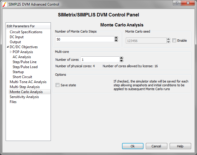
The Monte Carlo analysis allows you to investigate the effect of random parameter value changes on your circuit. The Monte Carlo analysis assumes that you have set up your circuit with statistical parameter distribution functions.
For more information, see the Monte Carlo Analysis topic.
| Parameters | |
| Number of Monte Carlo Steps | The number of steps, or simulations, to run |
| Monte Carlo Seed | The seed value for the Monte Carlo simulation. The seed value starts the pseudo-random number generator at a specific value. Subsequent seeds follow a predictable pattern, which makes the Monte Carlo simulation repeatable. |
| Multi-core | |
| Number of cores | The number of cores used for the simulation. The Pro and Elite licenses allow the use of 4 and 16 cores respectively. |
| Save state | If checked, SIMPLIS will save initial
conditions files with names which match the Monte Carlo seed values. You can
use the GenerateInitFile entry to
save the initial conditions files and the IncludeInitFile entry to include these
files. Important: You must enable and provide a starting seed
to include the initial conditions files.
|
Files Page
The Files page allows you to do the following:
- Assign a default testplan
- Customize the appearance of the simulation reports
- Add Pre-process and Post-process scripts to be run on every simulation
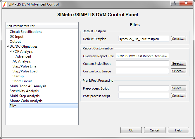
| Default Testplan: used when you select either DVM ▶ Run Schematic's Default Testplan or DVM ▶ Run Entire Schematic's Default Testplan from the menu bar. | |
| Default Testplan | Specifies the default testplan to be used with this schematic. |
| Report Customization: Options to customize the appearance of the DVM report | |
| Overview Report Title | The title used on the overview report. The titles for individual test reports can be changed with the HTMLTitle testplan entry. |
| Custom Style Sheet | Cascading Style Sheet (CSS file) to use with the DVM report |
| Custom Logo Image | Portable Network Graphics (PNG) file to use with the DVM report |
| Pre & Post Processing | |
| Pre-process Script | SIMetrix script to be executed immediately before launching each simulation; this allows you to change schematic values or analysis statements before running the test. Preprocess scripts are executed after all Objective entries are processed which allows users to override any schematic changes made by DVM. |
| Post-process Script | SIMetrix script to be executed immediately after each simulation successfully completes; this allows you to perform waveform manipulation and to create custom scalar and specification values. |