Pulse Load - Single Pure Current Pulse
The Pulse Load - Single Pure Current Pulse subcircuit models a single pulse without a resistive load. For a single current pulse load with a resistive component, see the Pulse Load - Single Current Pulse. In DVM, this load is not used in any test objectives, but you can set any managed DVM load to use this subcircuit with a PulsePure() call in the Load column of your testplan.
In this topic:
| DVM Information | Power Supply (Non-DVM) Information | |||||||
| Model Name | Pulse Load - Single Current Pulse | |||||||
| Simulator |
|
|||||||
| Parts
Selector Menu Location |
|
|||||||
| Symbol Library | SIMPLIS_DVM_ADVANCED.sxslb | power_supply_source_and_loads.sxslb | ||||||
| Model File | SIMPLIS_DVM_ADVANCED.lb | power_supply_source_and_loads.lb | ||||||
| Subcircuit Name |
|
POWER_SUPPLY_LOAD_PULSE_PURE | ||||||
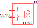
| Symbols |
|
|
||||||
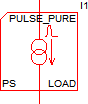
| Schematic - 2 Terminal |
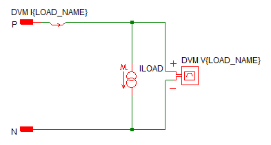
Note: Power Supply probes will not have the "DVM" prefix.
|
|||||||
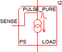
| Schematic - 3 Terminal |
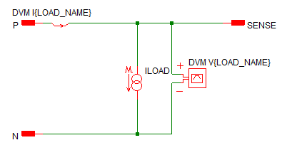 Note: Power Supply probes will not have the "DVM" prefix.
|
|||||||
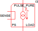
| Schematic - 4 Terminal |
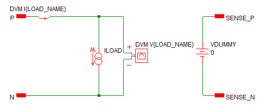 Note: Power Supply probes will not have the "DVM"
prefix.
|
|||||||


Pulse Load - Single Pure Current Pulse Parameters
The table below explains the parameters used in the Pulse Load - Single Pure Current Pulse subcircuit.
| Parameter Name | Default | Data Type | Range | Units | Parameter Description |
| FALL_TIME | 50u | Real | min: 0 | s | The pulse fall time in seconds |
| FINAL_CURRENT | 750m | Real | min: 0 | A | The final current for the load. The Pulse Load - Single Pure Current Pulse continues at this current for all simulation times greater tha TIME_DELAY+RISE_TIME. This can be a numeric value or a symbolic value, such as a percentage of full load. |
| LOAD_NAME | LOAD | String | n/a | n/a | Name of the DVM load. This name cannot contain spaces. |
| PULSE_CURRENT | 250m | Real | min: 0 | A | The pulsed current in amps. The pulse current can be a numeric value or a symbolic value, such as a percentage of full load. |
| PULSE_WIDTH | 200u | Real | min: 0 | s | The pulse width in seconds. Note that DVM considers the pulse width to be the duration of the pulse at the PULSE_CURRENT. |
| RISE_TIME | 100u | Real | min: 0 | s | The pulse rise time in seconds |
| START_CURRENT | 0 | Real | min: 0 | A | The starting current for the load. This can be a numeric value or a symbolic value, such as a percentage of full load. |
| TIME_DELAY | 10u | Real | min: 0 | s | The time delay before the pulse initiates |
DVM Testplan Entry for the Pulse Load - Single Pure Current Pulse
To set any managed DVM load to a Pulse Load - Single Pure Current Pulse subcircuit, place a PulsePure() testplan entry in the Load column.
The PulsePure() testplan entry has the following syntax with the arguments explained in the table below.
PulsePure(REF, START_CURRENT, PULSE_CURRENT, FINAL_CURRENT)
PulsePure(REF, START_CURRENT, PULSE_CURRENT, FINAL_CURRENT, OPTIONAL_PARAMETER_STRING)
where:
| Argument | Range | Description |
| REF | n/a | The actual reference designator of the DVM load or the more generic syntax of OUTPUT:n where n is an integer indicating a position in the list of DVM loads. |
| START_CURRENT | min: 0 | The starting current for the load. This can be a numeric value or a symbolic value, such as a percentage of full load. |
| PULSE_CURRENT | min: 0 | The pulse current for the load. This can be a numeric value or a symbolic value, such as a percentage of full load. |
| FINAL_CURRENT | min: 0 | The final current for the load. This can be a numeric value or a symbolic value, such as a percentage of full load. |
| OPTIONAL_PARAMETER_STRING | n/a |
Parameter string with a combination of one or more timing parameters:
|
* If more than one parameter is specified, join the parameter key-value pairs with a space, as shown in the example below. The order of the parameter names does not matter.
Timing
The timing for the Pulse Pure Load is determined by the following parameters.
- TIME_DELAY
- RISE_TIME
- PULSE_WIDTH
- FALL_TIME
Timing parameters can be assigned using the optional parameter string as shown in the following examples.
Symmetric Pulse DVM Example
This example shows a symmetric pulse with equal rise and fall times. The final current is the same as the starting current.
| *?@ Load |
|---|
| PulsePure(OUTPUT:1, 1, 5, 1, TIME_DELAY=25u RISE_TIME=25u PULSE_WIDTH=100u FALL_TIME=25u) |
The results of this testplan entry are shown below:
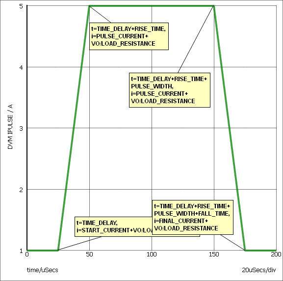
| Annotation | Value |
| X0 | TIME_DELAY |
| X1 | TIME_DELAY + RISE_TIME |
| X2 | TIME_DELAY + RISE_TIME + PULSE_WIDTH |
| X3 | TIME_DELAY + RISE_TIME + PULSE_WIDTH + FALL_TIME |
| Y0 | START_CURRENT |
| Y1 | PULSE_CURRENT |
| Y2 | PULSE_CURRENT |
| Y3 | FINAL_CURRENT |
Asymmetric Pulse DVM Example
The following example sets the first DVM managed load to a Pulse Load - Single Pure Current Pulse, with a starting current of 1A, a pulse current of 5A and a final current of 4.5A. Note the rise and fall times are not the same and the pulse does not have to return to the starting current value.
| *?@ Load |
|---|
| PulsePure(OUTPUT:1, 1, 5, 4.5, TIME_DELAY=25u RISE_TIME=25u PULSE_WIDTH=75u FALL_TIME=50u) |
The results of this testplan entry are shown below:
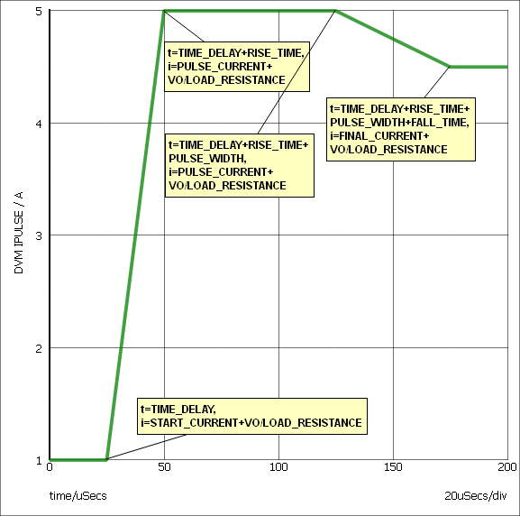
| Annotation | Value |
| X0 | TIME_DELAY |
| X1 | TIME_DELAY + RISE_TIME |
| X2 | TIME_DELAY + RISE_TIME + PULSE_WIDTH |
| X3 | TIME_DELAY + RISE_TIME + PULSE_WIDTH + FALL_TIME |
| Y0 | START_CURRENT |
| Y1 | PULSE_CURRENT |
| Y2 | PULSE_CURRENT |
| Y3 | FINAL_CURRENT |
Converting between DVM and Power Supply Loads
To change a Power Supply load to a DVM load, right click the symbol to bring up the context menu, and select the menu option: Upgrade to DVM Source/Load
To change a DVM load to a Power Supply load, right click the symbol to bring up the context menu, and select the menu option: Downgrade to SIMetrix/SIMPLIS Source/Load