SIMPLIS BJT Models
Any SPICE BJT model installed in the SIMetrix library can be converted for use in SIMPLIS. When a BJT is placed on a SIMPLIS schematic, a model parameter translation routine is invoked to automatically convert the SPICE model to a SIMPLIS model. During the model parameter translation process, SIMetrix/SIMPLIS automatically runs several SPICE simulations on the SPICE model and translates the SIMPLIS model parameters. After the Piecewise Linear (PWL) model parameters have been translated, the resulting BJT model will run in SIMPLIS.
In this topic:
Translating the BJT Parameters
When you place a BJT symbol on a schematic, the Translate BJT Parameters dialog opens for you to edit the default test conditions. The default test conditions are defined using the command shell menu . For additional information, see SIMPLIS BJT Options.
![]()
The following table describes the Translate BJT Parameters dialog test conditions.
| Test Condition | Default Value | Units | Description |
| SPICE Model | Q2N2222 | The SPICE model used to translate the SIMPLIS parameters. | |
| Model type | Translated | Invokes the model parameter translation algorithms. |
| Model level | 2 | Model complexity. For information on choosing the model level, see BJT Model Levels. | |
| Peak collector current | 50m | A | Peak collector current for this device. |
| Device is ON at time=0 | Unchecked | Sets the initial state of this device. |
SIMPLIS BJT Model Levels
The SIMPLIS BJT models support two levels: 1 and 2.
- Level 1 uses a SIMPLIS primitive switch to model the conduction of the BJT.
- Level 2 uses a Ebers-Moll model for the BJT.
SIMPLIS translates the SPICE model to a SIMPLIS model based on the model level chosen in the Translate NPN/PNP Parameters dialog. Although these models are internally saved as ASCII text, the following illustrations show the two model levels in a schematic form.
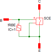
Level 1 Model
Level 1 models a BJT using a SIMPLIS primitive switch and a PWL base-emitter diode. This model is primarily useful if the BJT is used as a basic on/off switch, and the details of the saturation behavior are not critical.
Below is a schematic view of Level 1 model:
| Level 1 models these circuit elements | Level 1 Schematic | ||||
|
|
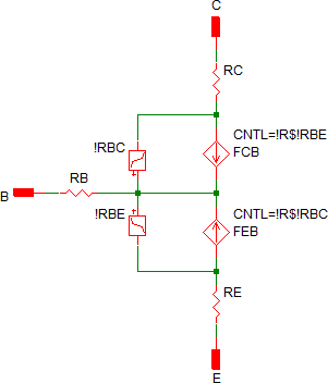
Level 2 Model
The Level 2 BJT model uses the Ebers-Moll BJT model.
Below is a schematic view of Level 2 model:
| Level 2 models these circuit elements | Level 2 Schematic | ||||||||||||
|
|
User-defined Models
The user-defined model uses parameters entered directly in the Edit BJT Parameters dialog without invoking the model translation algorithms. A BJT can be switched from an translated model to a user-defined model at any point; however the translated parameters are by default copied over to the user-defined parameters, replacing any user-entered values. You can disable this behavior in the SIMPLIS Options dialog by clearing the check box labeled Automatically copy translated parameters to User-defined parameter. You can access these options from the command shell menu . For more information, see SIMPLIS BJT Options.
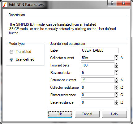
| Parameters | Default Value | Units | Description |
| Label: | USER_LABEL | Any descriptive text. Cannot contain whitespace characters. | |
| Model type: | User-defined | The values in this dialog are used literally. | |
| Collector current: | 50m | A | Peak collector current for this device |
| Forward beta: | 100 | The forward gain of the BJT transistor | |
| Reverse beta: | 5 | The reverse gain of the BJT transistor | |
| Saturation current: | 1E-15 | A | The transistor saturation current |
| Collector resistance: | 0 | Ω | The collector resistance |
| Emitter resistance: | 0 | Ω | The emitter resistance |
| Base resistance: | 0 | Ω | The base resistance |
User-defined model
The user-defined model is simply a level 2 model with user input of all parameters.
Below is a schematic view of a User-defined model:
| User-defined models these circuit elements | User-defined Schematic | ||||||||||||
|
|
Manually Generate and Customize BJT Models
You can customize or manually generate your own BJT models using a parameter string with multiple PARAM_NAME=PARAM_VALUE key-value pairs. The parameter names and their functions are described in the BJT Model Parameters section below. You can interpret the SIMPLIS parameter values from device datasheet specifications and curves.
You can compose the parameter string in a text editor, spreadsheet, or script. The order of the parameter names in the parameter string and the capitalization of the parameter names are irrelevant.
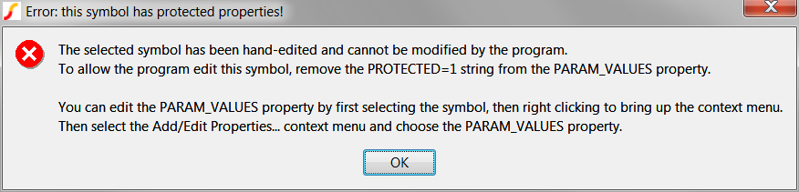
You can include a PROTECTED=1 key-value pair to prevent from translating a model and overwriting your manually generated parameters. The PROTECTED=1 key-value pair is not used in the simulation.
To customize or generate your own BJT model, follow these steps:
- Create a parameter string of multiple PARAM_NAME=PARAM_VALUE key-value pairs using your preferred text editor, spreadsheet or script.
- Add the PROTECTED=1 key-value pair to the parameter string.
- Translate BJT model and place it on a schematic.
- Right click on the symbol and select Edit/Add Properties....
- Double click on the PARAM_VALUES property.Result: The Edit Property dialog opens. At this point, you can change individual parameters in the Value box, or replace the entire default properties with the parameter string that you created in Step 2.
- To replace the entire string, follow these steps:
- Click in the Value box and type Ctrl A to select all of the existing parameter string, and press Delete.
- Copy the parameter string you completed in Step 2 and paste into the Value box.
- Click Ok.
- To change the name of your customized model, double click the VALUE property in the Edit Properties dialog, and change the name in the Value box.
- To return to the schematic, click Ok.
prop PARAM_VALUES parameter_stringwhere parameter_string is the set of key-value pairs that you created in Steps 1 and 2 above.
BJT Model Parameters
The following tables detail the parameters which define the electrical behavior of the BJT model. Several other parameters in the PARAM_VALUES property have no effect on the electrical behavior of the model. These parameters are used to populate the Translate BJT Parameters dialog box.
| Parameter Names | Default Value | Description |
| USE_EXTRACTED | 1 | This parameter switches to
model to either use the Translated parameters, or the User-defined
parameters. If you set this to 1, the model will use the parameters in
this table. Note: This parameter name is a misnomer carried over from the
other semiconductor devices. There are no Extracted BJT models in
SIMPLIS.
. |
| LEVEL | 2 | The level parameter. See SIMPLIS_BJT_Model_Levels for details. |
| ICE_PEAK | 50m | Peak collector current for this device |
| BF | 100 | The forward gain of the BJT transistor |
| BR | 5 | The reverse gain of the BJT transistor |
| IS | 1E-15 | The transistor saturation current |
| RC | 0 | The collector resistance |
| RE | 0 | The emitter resistance |
| RB | 0 | The base resistance |