4.0 What is a Symbol?
Symbols are one of the most complicated parts of SIMetrix/SIMPLIS. In this topic, you will learn what constitutes a symbol, how they are used, how they are updated on schematics, and how they are stored. Many misconceptions about symbols are covered and explained.
To download the examples for Module 4, click Module_4_Examples.zip
In this topic:
Key Concepts
This topic addresses the following key concepts:
Symbols have three primary functions:
- To define connectivity, and ideally the graphical symbol represents the functionality of the underlying electrical model.
- To pass parameters to the underlying electrical model.
- Allow easy parameter editing with parameter editing dialogs.
Symbols are made up of three components:
- Pins to define the electrical connectivity.
- Lines, Arcs, and Circles which describe the functionality of the underlying electrical model.
- Properties, some properties are descriptive, others, such as the REF and MODEL properties have electrical meaning. Properties can be protected so that users cannot modify the property value on the schematic.
Symbols are typically stored in one of four locations:
- A symbol library. Built-in symbols are stored in these libraries.
- In a schematic file. These symbols cannot be used outside this schematic.
- In a schematic component (.sxcmp) file. These symbols are used in other schematics and schematic component files.
- As a script file which creates the symbol on-the-fly. Several built-in symbols are created when you place them.
What You Will Learn
In this topic, you will learn the following:
- Where symbols are stored and how protected vs. unprotected property values are updated on the schematic.
- How to place hierarchical symbols on a schematic using a path relative to the parent schematic.
Some common misconceptions about symbols:
- Symbols are not models and models are not symbols.
- Symbols might not represent what you think - the electrical model can be subtly or dramatically different than the graphical depiction.
- The symbol placed on a schematic might be quite different than the library or schematic component version.
A few details for working with symbols:
- How to install and remove symbol libraries.
- How to edit symbols.
- The special symbol properties which determine the netlist content and other functionality.
Getting Started
Symbols and Models are often confused. In this topic you will learn the ins and outs of symbols, what symbols do in SIMetrix/SIMPLIS, and how to manage symbols.
Exercise #1: The User-Defined Diode
In this section you will run a simulation on the User-defined diode used as a synchronous rectifier in the SIMPLIS tutorial. The underlying model used by this diode symbol is a Piecewise Linear (PWL) resistor with two segments. In the following exercise, you will learn more about user-defined diodes and how these diodes might not conform to the graphical representation of a diode symbol.
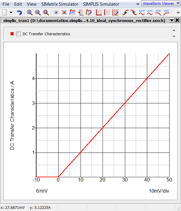
- Open the schematic 4.10_ideal_synchronous_rectifier.sxsch.Result: The schematic is a testbench with a single diode symbol, a driving voltage source, and an XY probe which plots the forward characteristics of the diode.
- Run the simulation.Result: The DC Transfer Characteristics of the user-defined diode are displayed on the waveform viewer. Note that the model is resistive, with a zero volt forward drop and a 10mΩ forward resistance.:
- Now double click on the diode symbol to view the User-defined diode
properties:Result: The Edit Diode : D1 Parameters dialog opens.
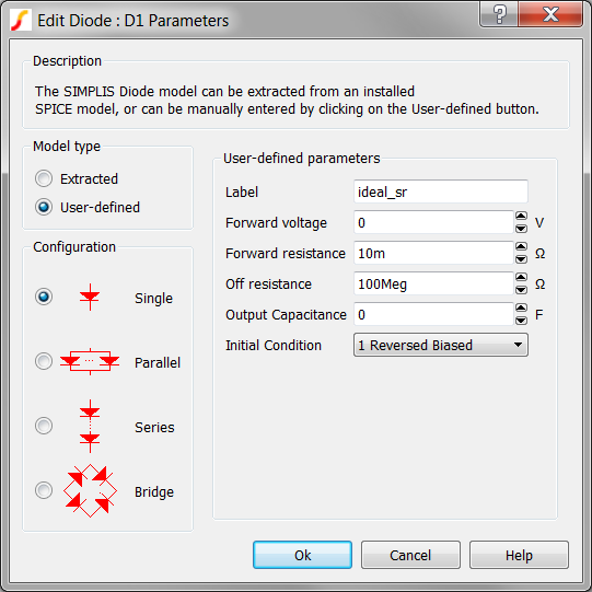
We have all been trained that all diodes have some finite, positive forward voltage drop. Mentally, a user sees the diode symbol and thinks "diodes have a forward drop and an exponential forward transfer characteristic." This example circuit was purposefully designed to show that user-defined diodes can have a zero-volt forward drop. Why would you want to have a zero-volt forward drop? Because this user-defined diode makes an ideal synchronous rectifier, which behaves just like a MOSFET with the "perfect" gate drive timing waveforms. Whenever the circuit connected to the diode attempts to force forward current through the diode, the diode behaves like a 10mΩ resistor. When the diode is in a blocking state, the resistance is 100MegΩ.
All semiconductor symbols used in SIMPLIS schematics call a electrical model which has PWL transfer characteristics. The model parameter extraction algorithms execute SIMetrix SPICE simulations on the SPICE model and curve fit a PWL model to the SPICE simulation curves. In contrast to the user-defined model in this exercise, a parameter extracted diode would have a forward voltage drop and three PWL segments, as opposed to the two segment model used in the user-defined diodes.
Common Attributes of Symbols
Symbols are made up of pins, which connect the symbol to the underlying model, graphical elements such as lines, arcs, and so on which describe the function of the underlying model, and of properties. Properties can be protected or unprotected, unprotected properties can be edited on a schematic, while protected properties cannot. Other common symbol attributes are:
Symbols Define Connectivity
The primary purpose of symbols is to connect models to wires, which, in turn, connect to other symbols. A good model designer would also design the graphical representation of the symbol to depict the underlying electrical model. While this seems obvious, consider a common item in power electronics - the capacitor. Capacitors often include equivalent series resistance and equivalent series inductance, yet the graphical representation of the capacitor symbol is often no different than the primitive capacitor which models a pure capacitance. Because symbols primarily define connectivity, and a capacitor is a two terminal device, a common symbol is often used. This often, and rightfully, confuses users. In section 3.0.2 What Actual Device is Simulated in SIMPLIS? you learned how to find exactly what device model is used in the simulation.
Symbols are not Models
Symbols are not models and models are not symbols. At SIMPLIS, we often hear users say "I placed this model on the schematic." In 99% of the cases, this is not true, as the getting started example demonstrated. You place symbols on the schematic and those symbols call electrical models, defined as a Schematic Component, as a ASCII text model from a library file, or defined with a script. Compared to models, symbols have a rather simple job to accomplish - to interconnect other symbols and as you will see, to pass parameters to the underlying electrical model.
Symbols May Pass Parameters to the Underlying Electrical Model
In section 3.0.2 What Actual Device is Simulated in SIMPLIS?, you learned how parameters stored on a symbol property were passed through to the electrical model using the SIMPLIS_TEMPLATE property. In the 5.1 Passing Parameters into Subcircuits Using the SIMPLIS_TEMPLATE Property topic, you will learn how to pass parameters to a subcircuit model. At this point, just remember that symbol properties store model parameters . Those symbol properties are passed to the model as model parameters via the SIMPLIS_TEMPLATE property.
Symbols May Have Parameter Editing Dialogs
The VALUESCRIPT and PARAMSCRIPT properties define the scripts which are called when a user interacts with the symbol. The VALUESCRIPT is called when the user double clicks on the symbol. If the user right clicks and executes the Edit Additional Properties... context menu, the PARAMSCRIPT is called. Adding parameter editing dialogs is covered in the 5.2 Parameter-Editing Dialogs topic.
Where are Symbols Stored?
Symbols can be stored in several locations:
- In a symbol library file - this is how most internal symbols are stored. Symbol library files are plain ASCII text files and have the file extension .sxslb.
- Locally on a schematic. Symbols stored locally cannot be used in other schematics. You can always copy local symbols from schematic to schematic if need be.
- As part of a Schematic Component file. A schematic component file includes both the symbol and the model in a schematic form. Schematic component files have the extension .sxcmp.
- As a script. Several internal symbols are dynamically generated when placed on the schematic. This implementation is used when the symbol has a variable number of pins and storing individual symbols for all logical combinations would be difficult. A few examples include SIMPLIS digital devices, bus rippers, and jumper symbols.
What Happens When you Place a Symbol on a Schematic?
When you place a symbol on the schematic, a copy of the library version is created and saved to the schematic file. This copy is called the instantiation and now resides in the schematic file. Because the symbols are copied to the schematic file, you can share a design with a colleague by sharing the schematic file alone. You can also add, modify, and delete symbol properties on the instantiated symbol without modifying the library version. This is important because the values for many symbol properties will be different than the default values saved in the library copy of the symbol. Consider the case of a large converter which might have 25 resistors, all with different values. The library version of the resistor symbol will have the default value of 1k, while each instantiation will have it's own local value for the resistance.
Symbols placed for hierarchical Schematic Component Files are treated differently. These symbols are read from the schematic component file and placed on the schematic. No local copy is saved.
A few examples will help demonstrate the difference between the instantiated symbol and the library version.
Exercise #2: The Diode Symbol
The User-defined diode is good example if the difference between instantiated the library versions of symbols. When you place a diode on a SIMPLIS schematic, the program adds several properties to the symbol. In this exercise you will examine the difference between the library symbol and the instantiated symbol. To get started, follow these steps:
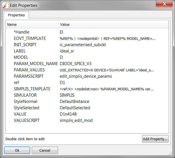
- On the 4.10_ideal_synchronous_rectifier.sxsch schematic, select the ideal_sr diode symbol.
- Press 5 to open the instantiated properties dialog.Result: The Edit Properties dialog opens displaying all the properties for the user-defined diode.
- Click Cancel on the dialog.
- Make sure the diode is still selected and press Shift+S to edit the
symbol.Result: The Junction Diode symbol opens in the symbol editor.
- Press P to open the symbol properties dialog.Result: The Edit Properties dialog opens displaying all the properties for the diode symbol.
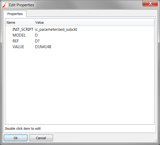
As you can see, the instantiated version of the symbol contains many more properties than the library version of the Junction Diode symbol. The additional properties re-purpose the Junction Diode symbol for use with the SIMPLIS simulator. In this case, the symbol is modified to call a subcircuit model and to pass parameters into that model.
Exercise #3: Schematic Component Symbols
In the 4.2 What is a Schematic Component File? topic, you will learn that schematic component files contain both a schematic and the symbol for the schematic. When you place a symbol for a schematic component, you are essentially telling the program "Go to this file named xxx and find the symbol and put it on the schematic here." Because you are referencing the file by name, there two ways to do this:
- With a relative path to the schematic.
- With a full file path, including the drive letter.
We cannot overemphasize the importance of using a relative path instead of a full path. When you use a full path, the design looses it's portability, as there are full path references to schematic component files. When the files are archived and opened from a different root directory, the schematic will not simulate because the referenced path doesn't exist.
In this exercise you will examine the difference between instantiated and library versions of the schematic component files. To get started, follow these steps:
- Open the 4.2_LLC_Closed_Loop.sxsch schematic.
- Select the schematic component modulator LLC_Modulator_Closed_loop in the lower left hand corner.
- Press 5 to open the instantiated properties dialog.Result: The Edit Properties dialog opens displaying all the properties for the user-defined diode.
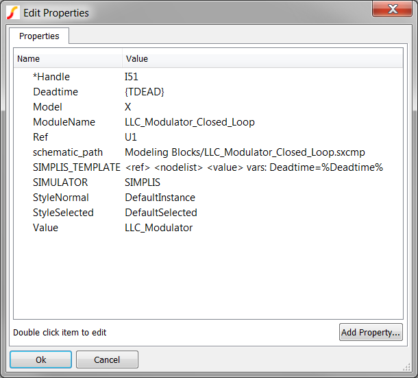 Note the schematic_path property. The
property value is Modeling Blocks/LLC_Modulator_Closed_Loop.sxcmp. This is
a relative path from the parent schematic. This path means "descend into the
Modeling Blocks directory, and find the schematic component
LLC_Modulator_Closed_Loop.sxcmp there."
Note the schematic_path property. The
property value is Modeling Blocks/LLC_Modulator_Closed_Loop.sxcmp. This is
a relative path from the parent schematic. This path means "descend into the
Modeling Blocks directory, and find the schematic component
LLC_Modulator_Closed_Loop.sxcmp there." - Click Cancel on the dialog.
- Make sure the LLC Modulator is still selected and press Shift+S to edit
the symbol.Result: The LLC_Modulator_Closed_Loop symbol opens in the symbol editor. This symbol is saved in the schematic component file: LLC_Modulator_Closed_Loop.sxcmp
- Press P to open the symbol properties dialog.Result: The Edit Properties dialog opens displaying all the properties for the LLC Modulator symbol.
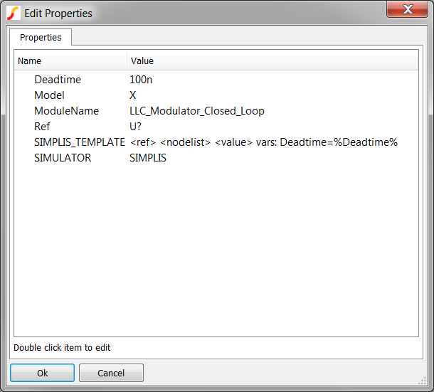
As with the Junction Diode, the instantiated symbol has additional properties, and some properties common to the both the library and instantiated symbols have different values. In particular, the deadtime parameter for the modulator is 100n in the library, but is parameterized on the instantiated symbol.
When are Properties Updated From the Library?
In the previous two exercises you learned that an instantiated symbol is a copy of the library symbol, but with modified and possibly additional symbol properties. The natural question arises: "What determines which properties are updated if the library version of the symbol changes?" The answer is fairly simple. Every property, pin, and graphical portion of the symbol is updated from the library except unprotected symbol properties. The unprotected symbol properties are typically used to store parameter information, such as the Deadtime property used in the LLC Modulator example. If you changed the Deadtime value on the symbol contained in the schematic component file, that change will not be reflected on the schematic.
Installing and Removing Symbol Libraries
A list of installed libraries can be found by opening the Symbol Manager. The SIMetrix/SIMPLIS menu bar: opens the following dialog:
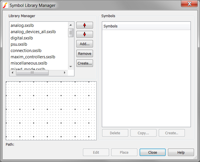
With this dialog, you can determine which libraries contain which symbols and add, remove, or create symbol libraries. The Help button links to a comprehensive help topic on the use of the Symbol Manager.
You can also install symbol libraries by the "drag-and-drop" method. Simply open a Windows Explorer window to the location of the symbol library file, and drag-and-drop the file to the SIMetrix/SIMPLIS command shell window. No message is given after you drop the symbol library file, the symbol library is installed quietly. You can always check the installed symbol libraries with the Symbol Manager.
Reserved Symbol Properties
The netlisting process was described in section 3.0.1 What Happens When You Press F9?. In that topic, the REF, MODEL, TEMPLATE and SIMPLIS_TEMPLATE properties were covered in some detail. The SIMPLIS_TEMPLATE property was covered in detail in the 3.0.2 What Actual Device is Simulated in SIMPLIS? topic. Several other special symbol properties exist:
| Symbol Property Name | Function |
| VALUESCRIPT | The script name which is called when a user double clicks on the symbol or presses F7. This usually opens a dialog to edit parameter values. The parameter values are saved to the symbol as symbol properties. |
| PARAMSCRIPT | The script name which is called when the user right clicks and executes the Edit Additional Parameters... context menu option or presses the keyboard shortcut Ctrl+Alt+F7. |
| TEMPLATESCRIPT | Defines the script name to be executed to modify the symbol template value during netlist generation. |
| INITSCRIPT | The script name used to back annotate the initial conditions for this symbol. |
| PARAMS | Passes parameters to the subcircuit. This is the shortcut method and is not the preferred method. |
| LABELS | Reserved for parameter editing dialogs. |
| PARAMETERS | Reserved for parameter editing dialogs. |
| TABS | Reserved for parameter editing dialogs. |
| GROUPS | Reserved for parameter editing dialogs. |
| DESCRIPTIONS | Reserved for parameter editing dialogs. |
| SIMULATOR | Determines the symbol's compatibility with the SIMetrix or SIMPLIS simulators. |
| schematic_path | The full or relative path to the underlying schematic. Used for Schematic Component files. |
You should avoid using the special symbol properties for purposes other than their designated function. A full listing of special symbol properties can be found in the User's manual at: What is a Property?
Conclusions and Key Points to Remember
- Symbols define connectivity, and ideally the graphical symbol represents the underlying functionality of the electrical model.
- Symbols may pass parameters to the underlying electrical model.
- Symbols may have parameter editing dialogs which allow users to edit the parameters for the device.
- Symbols are not models and vice-versa.
- Symbols might not represent what you think - the electrical model can be subtly or dramatically different than the graphical depiction.
- Symbols may be stored in several locations, including a symbol library, on a schematic, or as a script file.
- Symbol libraries. can be installed and removed with the Symbol Manager.