Appendix 5.A - Passing Parameters into Subcircuits Using the PARAMS Property
To download the examples for Module 5, click Module_5_Examples.zip.
In this topic:
What You Will Learn
- How to pass parameters into subcircuits using the special PARAMS symbol property.
- Why the PARAMS property is not the preferred method for passing parameters into subcircuits.
Getting Started
There are several ways to pass parameters into subcircuits. In the previous topic, 5.0 About Parameters, you used the .GLOBALVAR statement to define a global parameter. A drawback to global parameters is that every instance uses the same parameter value. In this topic, you will learn how to pass parameters through the symbol-to-subcircuit interface, which allows you to pass the same parameter name with different values for each instance.
Passing the Parameter through the Symbol-to-Subcircuit Interface
In this exercise, you will learn how to do the following:
- Pass a parameter through the symbol-to-subcircuit interface using the PARAMS symbol property
- Define an default value for the FC parameter
- Update the instantiated symbols on the schematic
Exercise #1: Add the PARAMS Symbol Property
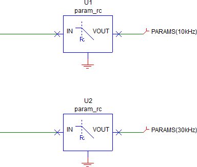
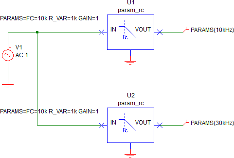
The schematic component param_rc.sxcmp used in this exercise requires a single parameter, with the parameter name FC. This parameter will set the filter's -3dB cutoff frequency. The example schematics are already prepared and ready to run, only the parameter passing part is missing.
The PARAMS symbol property is a special property which the netlister detects and uses to add parameters to the netlist instantiation line for the symbol. In this exercise you will add the PARAMS property to the param_rc.sxcmp symbol.
To add the PARAMS symbol property to the FC parameter, follow these steps:
- Open the schematic, 5.2_parametrized_rc_filters.sxsch .
- To add the PARAMS property to the param_rc.sxcmp symbol with a value of
FC=10k, follow these steps:
- Select U1, and then type the keyboard
shortcut Shift+S
to open the symbol. Result: The param_rc schematic component symbol opens in the symbol editor.
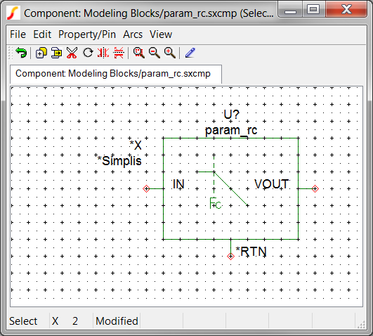
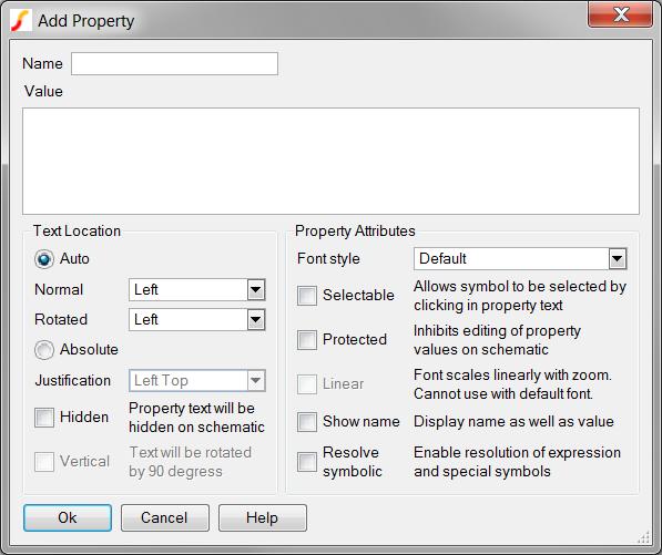
- From the Symbol Editor menu, select Property/Pin ▶ Add Property...
Result: The Add Property dialog opens.
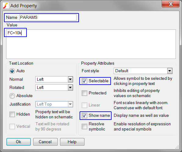
- In the Name field, type PARAMS.
- In the Value field, type FC=10k.
- Check the Selectable and Show name check boxes. Result: The configured Add Property dialog should appear as below:
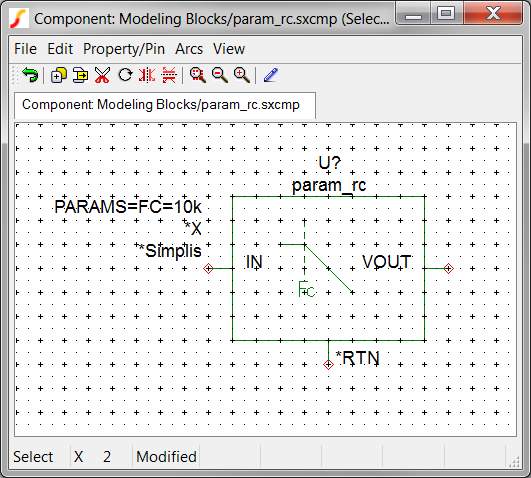
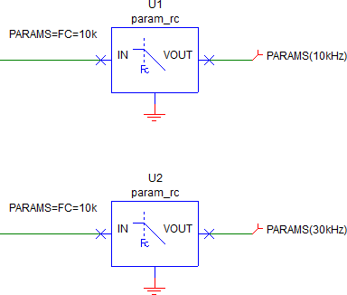
- Click Ok on the Add Property Dialog. Result: The PARAMS property is added on the left side of the symbol with the value FC=10k.
- Select U1, and then type the keyboard
shortcut Shift+S
to open the symbol.
- From the Symbol Editor menu, select File ▶ Save...
- Click Ok on the Save Symbol dialog to save the symbol to the component file, and then close the Symbol Editor window.
- To update the instantiated symbols on the schematic, follow these steps:
- Select U1.
- Press and hold the Ctrl key while selecting U2. Result: Both symbols for U1 and U2 are selected:
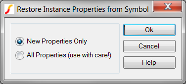
- Right click to bring up the context menu, and then select Restore
Properties...
Result: A dialog opens for you to confirm that you want to add the new properties to the instantiated symbols:
- Click Ok. Result: The schematic instances for U1 and U2 are updated with the new symbol property PARAMS:
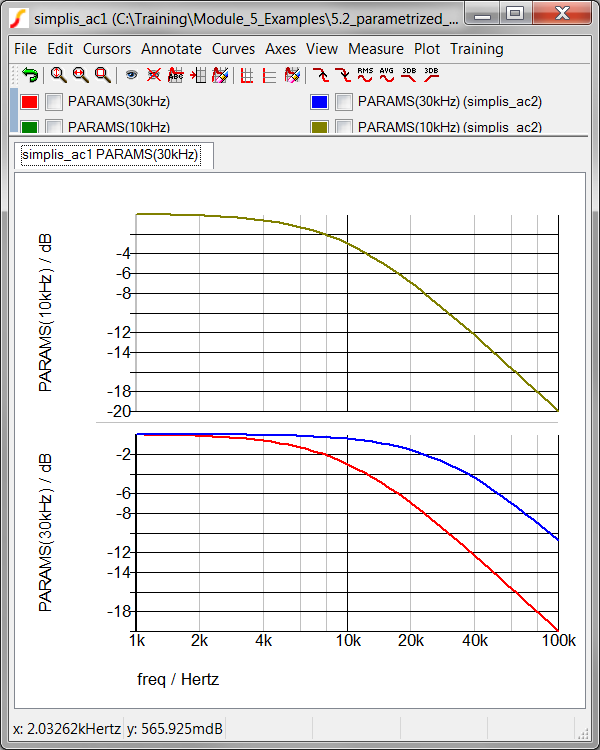
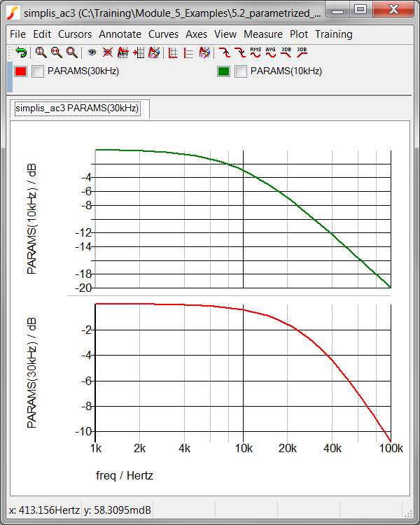
- Press F9 to run the simulation. Result: The design simulates in SIMPLIS and two gain curves are output, one for each of the two filters. The pole frequency is 10kHz for both filters because the passed parameters are identical for both U1 and U2.
Discussion: Exercise #1
In Exercise #1, you added a symbol property PARAMS to the symbol stored in the schematic component file. The PARAMS property is a special symbol property and the netlister handles this property differently than the other properties. When the symbol template is resolved and the netlist entry is made, the value of the PARAMS property (in this case, FC=10k) is added to the instantiation line for the symbol after the vars: keyword. In the next exercise you will examine how the PARAMS value can be different on each instantiated symbol and how the resulting netlist entry and simulation results are affected.
Defining Different Values for Instantiated Symbols
In this section, you will change the value of PARAMS property and look at how the netlist and the simulation results change.
Exercise #2: Edit the PARAMS property
To edit the property PARAMS value on the U2 instantiated symbol, follow these steps:
- Double click on the PARAMS property on the left side of the U2 symbol.
Result: The Edit Property dialog opens.
- Change the Value to FC=30k.
- Click Ok.
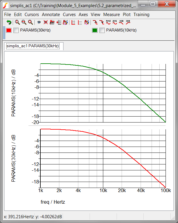
- Press F9 to run the simulation. Result: The simulation executes and a new set of curves are overlaid on the first set. The pole frequency for the filter U2 is now 30kHz. The filter U1 has the same 10kHz pole frequency.
Discussion: Exercise #2:
You have now edited the local, instantiated value of the PARAMS property on one of the rc_filter.sxcmp schematic components. This edit passes 30kHz as the pole frequency parameter into the subcircuit for the U2 instantiation. In the next exercise, you will see how the netlist is affected by this change.
Exercise #3: View the Netlist
- From the SIMetrix/SIMPLIS menu bar, select Edit Netlist (before
preprocess). Result: The netlist opens in Notepad++.Note: If you have not changed the default text editor, the netlist will open in notepad.exe.
- Scroll down to line 23, where the instantiation line U1 is located.
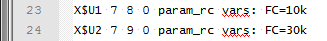 Result: The vars: keyword and the FC=10k parameter name-value pair are being passed to the subcircuit. The second instantiation, for U2 is being passed the FC=30k parameter name-value pair.
Discussion: Exercise #3:
The key concept here is that a single parameter can passed into the subcircuit on the netlist instantiation line. Multiple instantiations can use the same subcircuit (param_rc) with different parameter values. This allows a single schematic model to be configured with the passed parameter value.
Passing Multiple Parameters
The param_rc schematic component file uses three parameters:
- Two parameters are defined with .GLOBALVAR statements in the command window of the parent schematic.
- The other parameter is passed through the symbol-to-subcircuit interface using the PARAMS property.
You can pass multiple parameters using the PARAMS symbol property, and in the next exercise you will add the two global parameters to the PARAMS property.
Exercise #4: Add Additional Parameters to the PARAMS property
To open the symbol for the schematic component param_rc.sxcmp and add the two global parameters, follow these steps:
- Select U1, and then type the keyboard
shortcut Shift+Sright click, and
then select Edit Symbol... to open the symbol. Result: The param_rc schematic component symbol opens in the Symbol Editor.
- Click on the PARAMS property. Result: The PARAMS property changes from black to blue, indicating the property is selected.
- Press F7 to edit the PARAMS property.
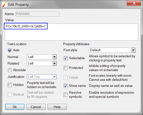
- In the Value field, after the FC=10k, add R_VAR=1k
GAIN=1.Note: There are spaces between each property name-value pair.Result: The final property should appear as follows:
- Click Ok.
- From the Symbol Editor menu, select File ▶ Save...
- Click Ok on the Save Symbol dialog to save the symbol to the component file, and then close the Symbol Editor window.
- To update the instantiated symbols on the schematic, follow these steps:
- Select U1, and then hold down the Ctrl key while selecting
U2. Result: Both symbols for U1 and U2 are selected:
- Right click to bring up the context menu, and select Restore
Properties...
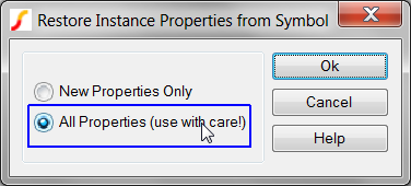
Result: The same dialog seen in Exercise #1 opens, asking you to confirm the action.
- Select the All Properties (use with care!) radio button. Important: Because the PARAMS property already exists, you need to select the All Properties (use with care!) radio button in order to revert the symbol to the version stored in the .sxcmp file. In the process, this overwrites the FC=30k parameter name-value pair set in Exercise #2.
- Click Ok. Result: The schematic instances for U1 and U2 are reverted to the symbol saved to the schematic component file.
- Select U1, and then hold down the Ctrl key while selecting
U2.
- Press F9 to run the simulation. Result: The design fails to simulate, and the netlist preprocessor outputs four errors to the SIMetrix/SIMPLIS command shell window:
*** ERROR *** ( 5.2_parametrized_rc_filters.net): Parameter 'R_VAR' for subcircuit instance 'X$U1' has already been defined as a global parameter
*** ERROR *** (5.2_parametrized_rc_filters.net): Parameter 'GAIN' for subcircuit instance 'X$U1' has already been defined as a global parameter
*** ERROR *** (5.2_parametrized_rc_filters.net): Parameter 'R_VAR' for subcircuit instance 'X$U2' has already been defined as a global parameter
*** ERROR *** ( 5.2_parametrized_rc_filters.net): Parameter 'GAIN' for subcircuit instance 'X$U2' has already been defined as a global parameter
Discussion: Exercise #4
These errors tell you that once a parameter name is defined to be global, the name is reserved and cannot be used as a local parameter name. When you added model parameter names to the PARAMS property, you defined parameters local to the param_rc.sxcmp schematic component. These errors protect you from simulating a design with two different parameter values, one global and one local.
Exercise #5: Correct the Errors
To correct these errors, you need to comment out the .GLOBALVAR parameters and change the value of the FC parameter for U2 to 30k. To make these changes, follow these steps:
- On the 5.2_parametrized_rc_filters.sxschschematic, press F11 to open the command (F11) window.
- Comment out the two remaining .GLOBALVAR statements. Result: The three .GLOBALVAR statements are commented out:
*.GLOBALVAR R_VAR=1k
*.GLOBALVAR GAIN=1
*.GLOBALVAR FC=10k
- Double click on the PARAMS property for U2.
- Change the PARAMS property value to FC=30k R_VAR=1k GAIN=1.
- Close the graph window.
- Press F9 to run the simulation. Result: The simulation executes as expected. The pole frequency of the filter U2 is 30kHz.
Exercise #6: View the Netlist with the Passed Parameter String
- From the SIMetrix/SIMPLIS menu bar, select Edit Netlist (before
preprocess). Result: The netlist opens in Notepad++.
- Scroll down to line 23, where the instantiation line U1 is located.
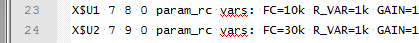 Note: The vars: keyword and the FC=10k R_VAR=1k GAIN=1 parameter string are being passed to the first subcircuit. The second instantiation, for U2 is being passed the FC=30k R_VAR=1k GAIN=1 parameter string. these parameters configure the values in the param_rc subcircuit.
Discussion: Exercise #6
The key concept here is that multiple parameters can be passed on the netlist instantiation line. Individual instantiations can use the same subcircuit (param_rc) with different parameter values. This allows a single subcircuit model to be used in multiple instantiations where each instantiation can be configured with different parameter values.
Conclusions and Key Points to Remember
- The PARAMS property is a special symbol property built-into SIMetrix/SIMPLIS. The netlister reads the property value and concatenates the netlist instantiation line with the PARAMS property value preceded with a vars: keyword. This effectively passes the parameter string into the instantiation as a set of parameters.
- A parameter string is an array of parameter name-value pairs, such as FC=30k R_VAR=1k GAIN=1. Parameter strings are used extensively in SIMetrix/SIMPLIS.
- The PARAMS property is easy to add to a symbol and offers a quick way to parameterize a subcircuit. That said, none of the built-in symbols use the PARAMS property to pass parameters to the underlying subcircuit. It is primarily used to temporarily pass parameters through the symbol-to-subcircuit interface.
The recommended way to pass parameters is described in the 5.1 Passing Parameters into Subcircuits Using the SIMPLIS_TEMPLATE Property topic.
Module Evaluation Form
At the end of the module, please fill out the Module # 5 Evaluation form.