2.3 Edit Multi-Level Models
This section of the tutorial explains how to edit multi-level models. You will start with the schematic that you saved in 2.2 Edit Standard Component Values and then change more component values for this design.
In this topic:
Key Concepts
This topic addresses the following key concepts:
- Inductors and Capacitors used in SIMPLIS can have multiple model levels. A model level represents the modeling complexity of the device; for example, a single capacitor symbol can model an ideal capacitor or represent a more complex model such as a capacitor with ESR and ESL.
- The multi-level lossy inductor model has a built-in high frequency limit. At frequencies above the corner frequency, the inductor becomes resistive.
What You Will Learn
In this topic, you will learn the following:
- How to edit symbols and change values on multi-level models.
- How to change the model level.
2.3.1 Change Capacitor Model Level and Value
Both the capacitor and inductor in this design are multi-level models, where the model level determines the parasitic elements included in the model. Four model levels, 0 through 3, exist for the capacitor.
- A level 0 capacitor is ideal and no ESR, ESL or leakage is modeled.
- As the level number increases, parasitic elements are added to the model.
- To learn more about the four model levels, click the Help button on the editing dialog to open the topic for the capacitor model.
This design is already set to a level 1 model. To change the output capacitor value, follow these steps:
- Double click the C1 symbol. Result: The Edit Multi-Level Capacitor dialog opens.
- Change the Capacitance value to 220u as shown below.
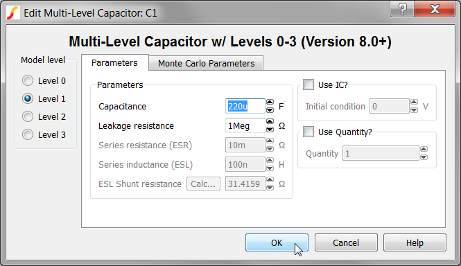
- Click Ok.
2.3.2 Change Inductor Model Level and Value
The inductor used in this design is also a multi-level model. The inductor has two model levels:
- Level 0 represents a pure inductor.
- Level 1 adds an equivalent series resistance (ESR).
Both inductor model levels have a parallel shunt resistance that limits the high-frequency response of the inductor. This is important for reasons that will become apparent later in the tutorial; for now, however, remember that the inductor has a built-in upper frequency limit and, at frequencies above this limit, the inductor becomes a resistor, reflecting the real behavior of the inductor.
To automatically calculate the shunt resistance value from the corner frequency, click on the Calc... button in the editing dialog.
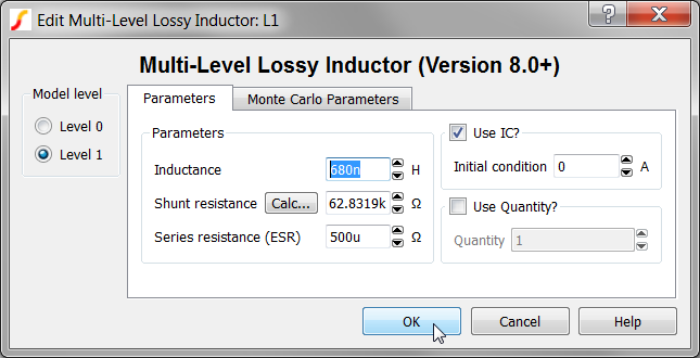
The inductance value for this design is 680nH. To change the inductor value, follow these steps:
- Double click the L1 symbol. Result: The Edit Multi-Level Lossy Inductor dialog opens.
- Change the Inductor value to 680n as shown below.
- Next you will change the inductor Shunt resistance parameter. To change the shunt
resistance, follow these steps:
- Click on the Calc... button.Result: The Calculate New Shunt Resistance dialog opens with the 680nH inductance value copied from the main dialog into the Calculate New Shunt Resistance dialog. The dialog has a built-in calculator function which calculates the new shunt resistance value based on the inductance and the desired frequency. You can change the Frequency entry and see the Shunt Resistance value change.
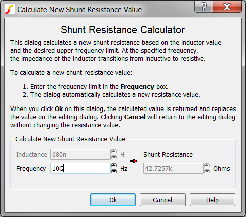
- The default frequency value of 10GHz is suitable for almost all switching power
applications. This is the frequency above which the inductor will become resistive.
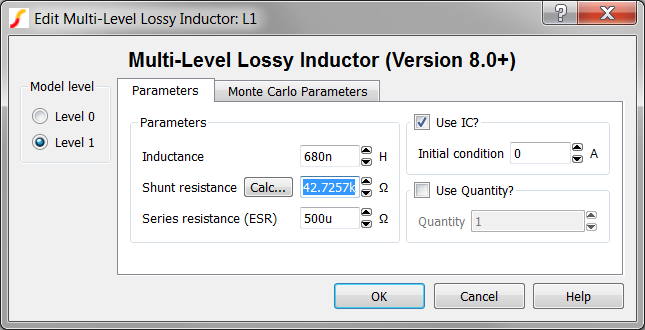
Click Ok on the Calculate New Shunt Resistance dialog to save the value to the
Edit Multi-Level Lossy Inductor dialog.Result: The calculated shunt resistance value of 42.7257kΩ is returned to the Edit Multi-Level Lossy Inductor dialog.
- Click on the Calc... button.
- Click Ok.
2.3.4 Save your Schematic
To save your schematic, follow these steps:
- Select .
- Navigate to your working directory where you are saving your schematics.
- Save the file as 2_my_buck_converter.sxsch.
- When prompted to overwrite the existing file, click Yes.Note: You will use this schematic in the next section, 2.4 Edit Parameter-Extracted Models.