4.2 What is a Schematic Component File?
Schematic component files are one of the most powerful concepts in SIMetrix/SIMPLIS. These files are effectively a container for both a schematic and a symbol to connect that schematic to a parent schematic. This system creates a modular design where all symbols are stored in the component files, meaning a design can be archived by archiving the test schematics and the schematic component files.
To download the examples for Module 4, click Module_4_Examples.zip
What You Will Learn
- Schematic component files are a combination of a schematic and a symbol, saved in a single file with extension .sxcmp.
- Schematic component files are implemented as subcircuits.
- Parameters can be passed into the underlying schematic using the SIMPLIS_TEMPLATE line like other subcircuits.
- There is no way to protect, lock, or otherwise encrypt the content of a schematic component file.
Getting Started
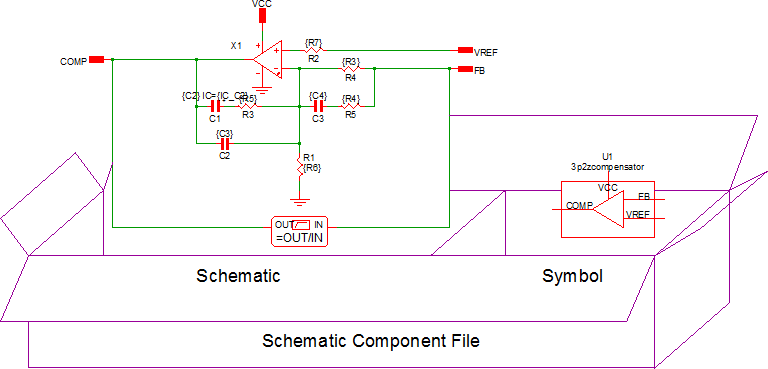
In the previous two topics, symbols and models were covered separately. A schematic component file is the combination of the electrical model, in a schematic form, and the symbol which calls the model. The extension .sxcmp is reserved for schematic component files. Using the compensator from the SIMPLIS Tutorial buck converter schematic, the schematic component file can be visualized as follows:
Exercise #1: Symbols are Stored Inside the Schematic Component File
The schematic 4.2_LLC_Closed_Loop.sxsch will be used in this exercise. This schematic has the symbols for two schematic component files - the LLC_Modulator_Closed_Loop.sxcmp and the Gen_Opto.sxcmp placed on the schematic. The symbol for each schematic component file is stored within the file itself, as this exercise demonstrates.
- Open the schematic 4.2_LLC_Closed_Loop.sxsch.
- Select U2, the opto-coupler defined by the schematic component Gen_Opto.sxcmp.
- Press Ctrl+E to descend
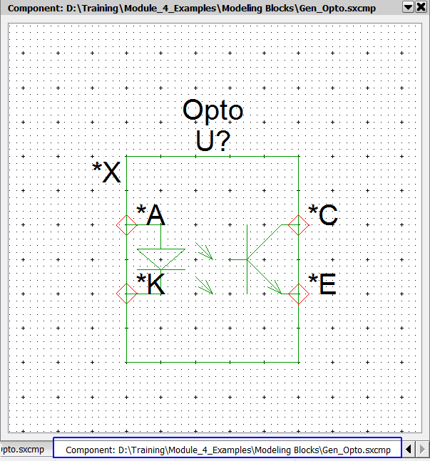
into the schematic of the Opto-Coupler.Result: The schematic opens and appears like any other schematic in SIMetrix/SIMPLIS.
- Press the keyboard shortcut S to open the symbol for the schematic component.Result: The symbol opens in the symbol editor. The window caption and tab title identifies that the symbol is saved to a schematic component file.
- Press Ctrl+S to save the symbol. Result: The Save Symbol dialog opens with the component file radio button selected: The File path name indicates the schematic component file to save the symbol to.
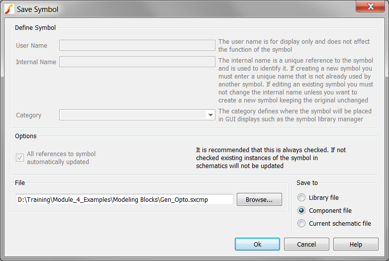
- Cancel the dialog.
Exercise #2: Schematic Component Files are Subcircuits
The fact that schematic component files are implemented as subcircuits is the most important concept behind schematic component files. This means is that every net inside each schematic component file is independent of every net outside the schematic component file. This also means that variables defined outside the schematic component file are not available inside the schematic component, unless the variables are explicitly passed into the schematic component via the SIMPLIS_TEMPLATE property.
Also, should two versions of the same schematic component file be placed on a schematic, the subcircuits are identical but completely independent of each other. By passing parameters into the schematic component, you can configure the same schematic component file to have different instantiated subcircuits.
In this exercise, you will see how the netlist entries for schematic components are created.
- Press F9 to run the simulation.
- From the menu bar, select .Result: The Netlist file opens in the text editor window.
- To find the Gen_Opto instantiation line and the subcircuit model, follow
these steps:
- Use the shortcut key Ctrl+F to open the search dialog.
- Type Gen_Opto in the search box.
- Click on the Find Next button.Result: The instantiation for the optocoupler is found first on line 125.

- Click on the Find Next button.Result: The document scrolls to line #220 where the subcircuit definition is located.
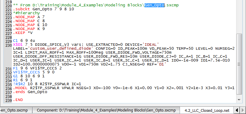
Notice that the model for the Gen_Opto is located in the netlist, and not in the deck file. Because the subcircuit definition for the Gen_Opto is included in the netlist, the netlist preprocessor doesn't search the model library for subcircuits with the name Gen_Opto. This prevents any naming collisions where a user might name a schematic component file to the same name as an internal subcircuit model. This also reinforces the principle that subcircuits defined in the netlist take priority over those in the global model library.
Passing Parameters to Models Implemented as Schematic Components
Using the SIMPLIS_TEMPLATE property, you can pass parameters to schematic components just like any other ASCII text based model. In the next exercise, you will see how the deadtime parameter is defined at the top level and is passed into the LLC_Modulator_Closed_Loop.sxcmp via the SIMPLIS_TEMPLATE symbol property.
Exercise #3: Passing Parameters to Schematic Components
- Navigate to the SIMetrix/SIMPLIS schematic editor window.
- Select the schematic tab with the top level schematic: 4.2_LLC_Closed_Loop.sxsch.
- Select U1, the LLC Modulator.
- Use the keyboard shortcut Shift+S
or right click and execute the context menu Edit
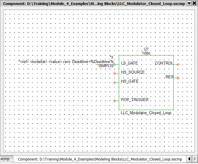
Symbol... to open the symbol.Result: The symbol editor opens with the schematic component symbol loaded:
- Press the keyboard shortcut P to open the symbol properties for the LLC
Modulator symbol.Result: The Edit Properties dialog opens:
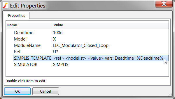
- The vars: Deadtime=%Deadtime% portion of the SIMPLIS_TEMPLATE passes the Deadtime symbol property as a model parameter Deadtime. To verify that the parameter is being passed into the netlist, navigate back to the netlist editor window which should have the netlist file open from the previous exercise.
- To search for LLC_ in the netlist file:
- Use the shortcut key Ctrl+F to open the search dialog.
- Type LLC_ in the search box.
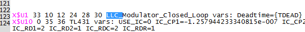
- Click on the Find Next button.Result: The document scrolls to line #123 where the instantiation line for U1 is located. The Deadtime variable is passed to the subcircuit with the value equal to the TDEAD parameter. TDEAD is set to 200ns with a .VAR statement in the top level F11 window.
The default SIMPLIS_TEMPLATE for schematic component files is <ref> <nodelist> <value>. This SIMPLIS_TEMPLATE is used for all schematic component files unless you provide your own SIMPLIS_TEMPLATE. To pass parameters to the subcircuit defined by the schematic component file, you must use the default SIMPLIS_TEMPLATE (<ref> <nodelist> <value>) followed by the vars: keyword and a space delimited list of subcircuit parameter key-value pairs. In this example, this portion of the SIMPLIS_TEMPLATE is vars: Deadtime=%Deadtime%.
Schematic Component Files Cannot Be Protected
Most models start life as schematic component files, as the schematic allows for fast design iterations; however, the schematic component file cannot be locked or protected. To protect or lock the design, an ASCII text model library file is created from the schematic component, which can then be encrypted. In section 4.4 Protecting Your Intellectual Property - Model Encryption, you will learn how to create ASCII and encrypted ASCII model files from a schematic component file.
Conclusions and Key Points to Remember
- Schematic component files are a combination of a schematic and a symbol, saved in a single file with extension .sxcmp.
- Schematic component files are implemented as subcircuits.
- Parameters can be passed into the underlying schematic using the SIMPLIS_TEMPLATE line like other subcircuits.
- There is no effective way to protect, lock, or encrypt a schematic component file.