Appendix 4.A - Symbols May Not Represent What You Think
To download the examples for Module 4, click Module_4_Examples.zip
In this topic:
Key Concepts
This topic addresses the following key concepts:
- Symbols can be modified to include models which behave differently than the graphical symbol representation.
- Templatescripts dynamically create models at run time.
What You Will Learn
In this topic, you will learn the following:
- How small modifications to symbols can drastically change their behavior.
Getting Started
Exercise #1: Symbols May Not Represent What You Think!
- Open the schematic 4.1_symbols_may_not_represent_what_you_think.sxsch.
- Press F9 to run the simulation.Result: The transient simulation executes and the waveforms for the resistor and capacitor voltages are shown. Clearly these voltages are not those of a resistor or a capacitor!
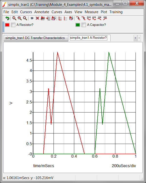
Extreme examples? Yes of course these are extreme examples. The point is that symbols and the models which they actually call, or otherwise put in the netlist don't have to correlate. In this example, two different methods were used to generate the resistor and capacitor models:
- The model used by the resistor symbol is generated with a templatescript: 4.1_make_phony_resistor.sxscr.
- The model used by the capacitor symbol is stored in a model library: 4.1_myCapacitor_model.lb.
Both files are located in the Module_4_Examples directory. The changes to the symbols are:
- For the resistor symbol, a TEMPLATESCRIPT property is added, with the property value: 4.1_make_phony_resistor.sxscr. When the netlist is created, the templatescript 4.1_make_phony_resistor.sxscr is called, the script then modifies the SIMPLIS_TEMPLATE property value. The templatescript replaces the resistor model with a PWL voltage source.
- The capacitor symbol has two modifications:
- The MODEL property has been changed to X, indicating a subcircuit model is used.
- The VALUE property has been changed to the subcircuit name: myCapacitor.
How these models are created or included in the simulation deck will be discussed in section 4.1 What is a Model?
Model Generation Using TEMPLATESCRIPTS
The model used by the resistor in the 4.1_symbols_may_not_represent_what_you_think.sxsch schematic was created with a template script. The script file is located in the schematic's working directory: C:/Training/Module_4_Examples/4.1_make_phony_resistor.sxscr. Creating models with templatescripts is outside the scope of this training course and only a brief introduction will be covered. The Script Reference Schematic Template Scripts has detailed instructions on how to create models using the templatescript method.
The template script used to create the model used by the resistor is:
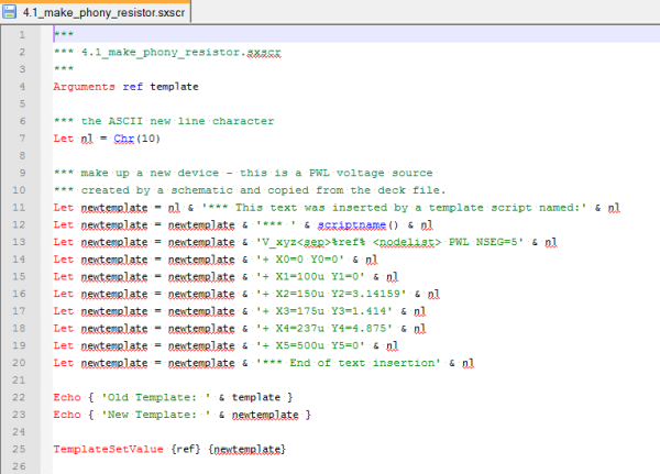
The script works as follows:
- Line 4 passes two string arguments into the script - that is the reference designator and the current template. The resistor has no template, so the template passed into the script is an empty string.
- Line 7 defines a variable nl as the ASCII character for a new line.
- Line 11 starts the new template definition with a new line followed by a comment line, then another new line.
- Lines 12 through 20 concatenate a new template, each line in the script creates a new line in the model.
- Lines 22 and 23 show the template values in the command shell. This is only for debug purposes - most template scripts would not include these debug statements.
- Line 25 is the business end of the script. Without setting the template value, the existing template value is unchanged. This line sets the schematic template to the newtemplate variable.
The first bullet in the What You Will Learn section defined a model as a primitive or a subcircuit model. The model created by the templatescript is a primitive model - that is, the reference designator begins with a character other than X. The capacitor model used in this topic is a subcircuit model as the reference designator begins with X.
Exercise #2: Verify the Resistor Model in the Netlist
In section 3.0.1 What Happens When You Press F9? you learned the templatescripts are executed during the netlist process. The netlister then evaluates the template as if the template was a static, fixed value, with the result being placed in the netlist. In this exercise you will verify the resistor model is placed in the netlist.
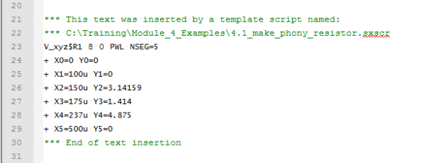
- From the menu bar, select SIMPLIS ▶ Edit
Netlist (before preprocess).Result: The netlist opens in Notepad++. The model generated is shown in the image below:
Conclusions and Key Points to Remember
- Symbols define connectivity, and ideally the graphical symbol represents the underlying functionality of the electrical model.
- Symbols may pass parameters to the underlying electrical model.
- Symbols may have parameter editing dialogs which allow users to edit the parameters for the device.
- Symbols are not models and vice-versa.
- Symbols might not represent what you think - the electrical model can be subtly or dramatically different than the graphical depiction.
- Symbols may be stored in several locations, including a symbol library, on a schematic, or as a script file.
- Symbol libraries. can be installed and removed with the Symbol Manager.