Schematic Styles
Styles manage the look and feel of the schematic and symbol editors. They control the colour of backgrounds, wires, components and annotations, along with the line type and thickness used.
Styles can exist either globally within your SIMetrix environment, or locally within a single schematic. If local, the styles will transfer with the schematic file so that they appear on other users machines with those styles. Although you are not forced to use another users local styling if you open a schematic with styling applied, as when you open such a file you will be given an option to use the local styling or apply your default global styling.
Elements on a schematic have at least two styles associated with them, one for how the element looks normally and one for how the element looks if it is selected. In some advanced cases there may be additional styles associated with a single element.
In this topic:
Style Editor
The Style Editor is made of four key components as shown in the figure below of the Edit Styles dialog. These components are: the style names, the line settings, the font settings and a preview window.
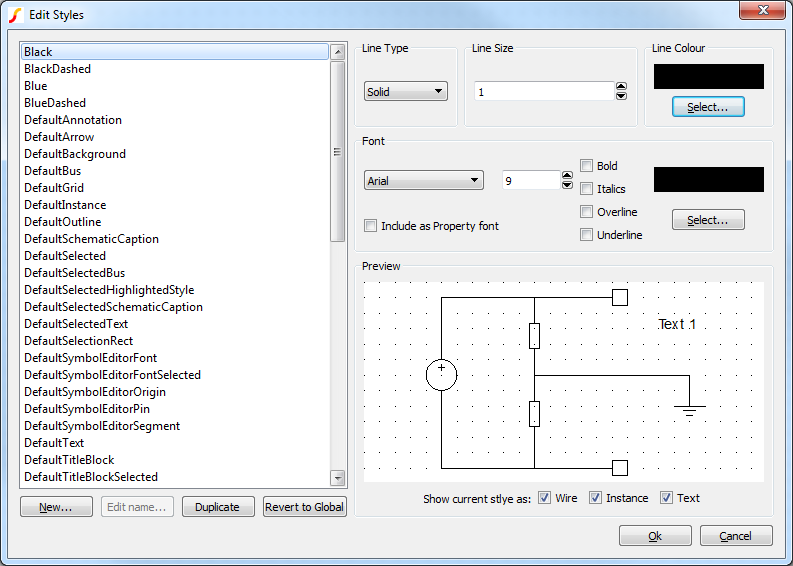 |
The Edit Styles dialog. Each style listed in the left hand panel of names has settings for the lines and fonts used. |
To edit a style, first open the style editor by going to the menu item in the schematic editor. This will allow us to edit the styles used on the schematic currently open. To change the styles globally across the program for all schematics, we would use the menu .
Next select the style to change from the left hand list of style names. When selected, the right hand panel will show the line and font settings used by this style. The preview window may also update, this is covered more in Preview Window.
The line and font settings can now be changed for this style. In some cases, such as wires, line annotations and text annotations, you may only be interested in editing either the line or font settings. For components, you may wish to change both.
To create a new style, use the New... button at the bottom of the style names list. Alternately you can duplicate an existing style by selecting the style to duplicate and pressing the Duplicate button. Duplicated styles can have their names changed using Edit name..., whilst local styles that appear in the global style library can be reverted to their global settings by selecting the style and pressing Revert to Global.
Line Settings
There are settings for line type, line size and line colour.
The line type has the options of: Solid; Dash; Dot; Dash-dot and Dash-dot-dot.
The line size is a numeric value. A size of 1 is one pixel wide and is commonly used throughout the program. Typically most lines would not need to have a line size above 3, with the majority being size 1.
The line colour selection box allows for different ways of inputting the required colour.
Font Settings
There are settings for font name, font size, font decoration and font colour.
The font name drop down box provides a list of available fonts.
The font size is a numeric value. The preview window will demonstrate the relative size of the font to the schematic.
The check boxes of bold, italics, overline and underline allow additional font styling and decorations to be applied.
The colour selection box allows for different ways of inputting the required colour.
The Include as Property Font check box allows the styles font values to be added to possible style overrides for symbol instance properties. This is covered more in Advanced Style Settings.
Preview Window
By default, the preview window will display an example schematic using the currently selected style. In the figure at the top for example, the line settings have been used to draw both the wires and symbol instances, whilst the font settings have been used for the text. The background and grid marker colours come from the styles DefaultBackground and DefaultGrid.
The preview window can be set to allow the current style to only edit some of the preview output. To do this, deselect the tick boxes below the preview window. If deselected, the wires will be drawn using DefaultWire, the symbol instances using DefaultInstance and the text using the font information from DefaultInstance.
Default Styles
The styles that are automatically used within the schematic editor by default are editable and are named with the prefix Default. Below is a table of where the default styles are used.
| Style Name | Where used | Uses |
| DefaultAnnotation | All annotations except arrows and standalone captions and free text. | All settings |
| DefaultArrow | The arrow annotation. | Line settings |
| DefaultBackground | The schematic and symbol editor background colour | Line colour |
| DefaultBus | Schematic buses. | Line settings |
| DefaultGrid | Grid used in schematic and symbol editor. | Line colour |
| DefaultInstance | Symbols in the schematic editor and their properties. | All settings |
| DefaultOutline | Used on all elements during a drag event to show where they were originally placed. | All settings |
| DefaultSchematicCaption | Caption annotation font. | Font settings |
| DefaultSelected | Used on all elements when they are selected, except for overridden exceptions. | All settings |
| DefaultSelectedBus | Selected override for buses. | Line settings |
| DefaultSelectedHighlightedStyle | Selected override for highlighted elements. | All settings |
| DefaultSelectedSchematicCaption | Selected override for schematic captions. | Font settings |
| DefaultSelectedText | Selected override for schematic free text. | Font settings |
| DefaultSelectionRect | Click and drag selection rectangle. | Line settings |
| DefaultSymbolEditorFont | Fonts used in the symbol editor. | Font settings |
| DefaultSymbolEditorFontSelected | Selected override for symbol editor fonts. | Font settings |
| DefaultSymbolEditorOrigin | Origin marker in the symbol editor. | Line settings |
| DefaultSymbolEditorPin | Pin markers in the symbol editor. | Line settings |
| DefaultSymbolEditorSegment | Symbol line segments used in the symbol editor. | Line settings |
| DefaultText | Free text annotation font. | Font settings |
| DefaultTitleBlock | Title block annotation. | All settings |
| DefaultTitleBlockSelected | Selected override for title block. | All settings |
| DefaultWire | Schematic wires. | Line settings |
| DefaultWireCreation | Schematic wires being created by the user. | Line settings |
| DefaultWireMoving | Schematic wires being moved around the schematic. | Line settings |
Additionally, there are legacy font settings used when importing schematics from earlier version of SIMetrix (pre-version 8), which are prefixed with Legacy.
Simplified Style Editing and Creation
Below are simplified methods for creating or editing styles.
Creating a Style for a Subset of Elements on a Schematic
To create a style for a selection of elements within a schematic:
- On the schematic, select the elements to create a new style for.
- Go to menu .
- Enter names to be used for the normal style and selected styles that are to be created and press OK.
- The Edit Styles dialog will now display, with only the two styles that were created on the previous step showing.
- Set the styles as required for both the normal and selected styles.
- Finish by pressing OK.
- The selected elements will now use the new styles.
Note: Styles applied to wires will only remain consistent when changed, if all connected wires share the same style.
Editing the Styles used by an Element or Selection of Elements
To change the style properties used by a particular element or group of elements:
- On the schematic, select the element or elements to change the style properties for.
- Go to menu .
- The Edit Styles dialog will now display, with only the styles used by the selected elements showing in the styles list.
- Make the changes to the styles as required.
- Finish by pressing OK.
- All elements using those styles will now be updated on the schematic with those changes. Changes are made to the local styles.
Changing the Styles used by an Element or Selection of Elements
- On the schematic, select the element or elements to change the style properties for.
- Go to menu for changing the normal style, or for changing the selected style.
- A list of available styles will appear.
- Choose the style to use and press OK.
- The selected elements will now change to use the requested style.
Advanced Style Settings
Below are advanced topics for using styles.
Property Fonts
Property fonts are overrides to the standard font used for properties within a symbol instance. Any style can be added to the available property fonts by selecting the Include as Property Font checkbox. Checking this on a local style will make the style available to only properties within that schematic, whilst checking it on a global style will make it available to all schematics.
- Right clicking on symbol instance in the schematic
- Click Edit/Add Properties...
- The Edit Properties dialog will appear, double click on the property to change.
- The Edit Property dialog will appear. Under Property Attributes, ensure the Font Style checkbox
- Default is deselected, then choose a font style, as shown in the figure below.
- Click OK on all open dialogs to close them and save the changes.
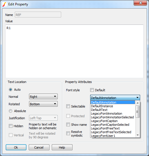 |
The Edit Property dialog, showing drop down list of override font styles. If default is selected, the font information in the symbol instance's style will be used, otherwise the selected override style will be used for the property text. |
Alternatively, the globally available property styles can be altered by using the dialog available in the Schematic Editor menu .
Manually Changing Styles Used
The styles used by an element can be manually changed by changing the style properties for that element. The properties to change are StyleNormal for the style used when displaying the element normally on the schematic. The style StyleSelected is used when the element has been selected by the user. The value of the property should correspond to a style name.
Symbol Fill Colour
If a symbol has been created with a filled region, the colour used for the filled region can be specified separately from the main style used by setting the StyleNormalInstanceFill property and setting the value to a style name. This can also added in the symbol editor at time of creation.
There is also a dialog that can be used to change the fill colour, in the Schematic Editor menu .
| ◄ Schematic Annotations | Schematic Grouping ▶ |