Example 2 -- 3-Phase Rectifier with Resistive Load
The circuit for Example 2 is a three-phase rectifier with resistive load, as shown in 9.4. It is made up of a three-phase ac voltage source in a Y-configuration which is rectified into a single load connected to the neutral line. The three voltage sources are modeled as cosinusoidal voltage sources of the same frequency with delays equal to 0, 1/3, and 2/3 of the period. The variables of interest are the three line-to-neutral voltages V(1), V(2), and V(3), and the load voltage V(4). The SIMPLIS input file for the circuit of Example 2 is shown in 9.5 . Waveforms for these four variables are plotted in 9.6.
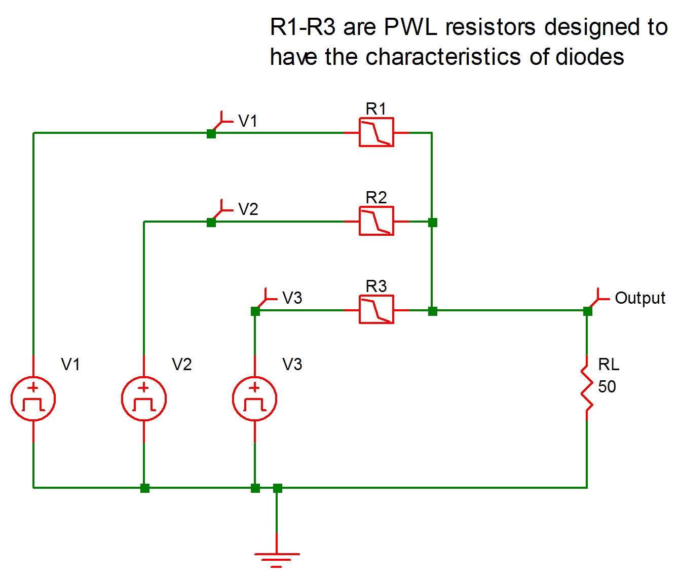 |
9.4 Three-phase Rectifier with Load |
9.5 Input File for Example 2 (as generated by SIMetrix)
* 3-Phase AC Voltage Source In A Y-Configuration
.PRINT  ALL
.OPTIONS  PSP_NPT=1001
.TRAN 2m 0
V1 1 0 COS VOFFSET=0 APEAK=5 FREQ=1k PDELAY=0
+ OFF_UNTIL_DELAY=NO DAMP_COEF=0
V2 3 0 COS VOFFSET=0 APEAK=5 FREQ=1k PDELAY=120
+ OFF_UNTIL_DELAY=NO DAMP_COEF=0
V3 4 0 COS VOFFSET=0 APEAK=5 FREQ=1k PDELAY=240
+ OFF_UNTIL_DELAY=NO DAMP_COEF=0
RL 2 0 50
!R$R1 1 2 R1$TP_SSPWLR IC=1
.MODEL R1$TP_SSPWLR VPWLR NSEG=2 X0=0 Y0=0 X1=1 Y1=5u
+ X2=1.1 Y2=1
!R$R2 3 2 R2$TP_SSPWLR IC=1
.MODEL R2$TP_SSPWLR VPWLR NSEG=2 X0=0 Y0=0 X1=1 Y1=5u
+ X2=1.1 Y2=1
!R$R3 4 2 R3$TP_SSPWLR IC=1
.MODEL R3$TP_SSPWLR VPWLR NSEG=2 X0=0 Y0=0 X1=1 Y1=5u
+ X2=1.1 Y2=1
.END
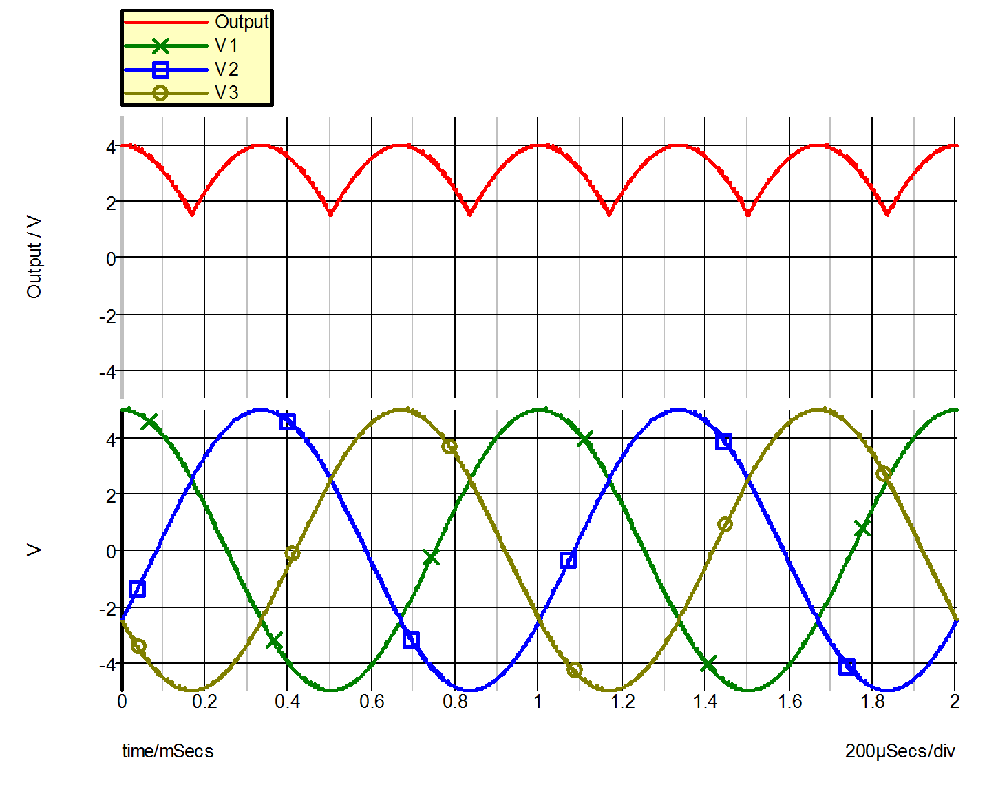 |
9.6 Waveforms for Example 2 |
| ◄ Example 1 -- Rectifier with RC load | Example 3 -- Operational Amplifier with Saturation ▶ |