Subcircuit Capacitors
The Subcircuit Capacitor symbols allows you to use a capacitor model implemented as a subcircuit model. There are two symbols, one without an initial condition and one with an initial condition. The symbol with the initial condition parameters was added to version 8.10b.
In this topic:
| Model Name: |
|
|||
| Simulator: |
|
This device is compatible with both the SIMetrix and SIMPLIS simulators. | ||
| Parts Selector Menu Location (SIMetrix): |
|
|||
| Parts Selector Menu Location (SIMPLIS): |
|
|||
| Symbol Library: | passives.sxslb | |||
| Model File (SIMetrix): | none - user supplied | |||
| Model File (SIMPLIS): | none - user supplied | |||
| Symbol: |
|
|||
| Multiple Selections: | Multiple devices can be selected and edited simultaneously. | |||
Editing the Subcircuit Capacitor
To configure the Subcircuit Capacitor, follow these steps:
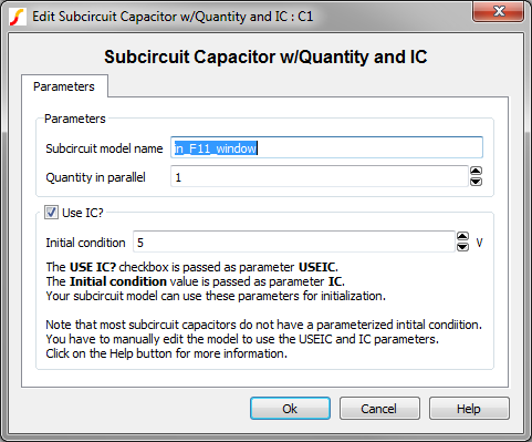
- Double click the symbol on the schematic to open the editing dialog to the Parameters tab.
- Make the appropriate changes to the fields described in the table below the image.
| Label | Description |
| Subcircuit model name | Subcircuit name. The subcircuit definition can be placed in the F11 window, a library file included with a .INCLUDE statement, or a library which is installed in the SIMetrix/SIMPLIS library system. You enter the actual name of the subcircuit in this box. |
| Quantity in parallel | Number of
subcircuit capacitors in parallel. Note: To
maximize simulation speed when using SIMPLIS, place a single symbol and
specify a value for this parameter instead of placing multiple
capacitors.
|
| Use IC? |
|
| Initial condition | Initial voltage of the capacitor at time=0 |
Quantity Implementation
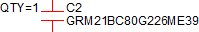
The Subcircuit Capacitor model has a quantity parameter, QTY, which specifies the number of capacitors in parallel. Configuring the capacitor as a number of capacitors in parallel minimizes the number of reactive circuit elements in the model and, therefore provides a maximum simulation speed.
The implementation of the quantity parameter uses a "DC Transformer" technique where the capacitor's terminal current is multiplied by a constant using a Current Controlled Current Source (CCCS). This technique effectively divides all resistance and inductance values by the quantity parameter (QTY) and multiplies the capacitance by that same value.
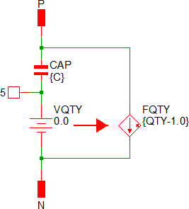
A schematic of the quantity implementation for a Subcircuit Capacitor is shown below, where CAP is the subcircuit capacitor model:
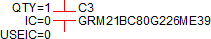
Initial Conditions
- USEIC
- IC
Examples
The test circuit used to generate the waveform examples in the next section can be downloaded here: simplis_034_1stordfilter_example.sxsch.
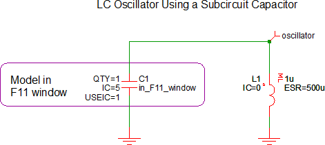
The subcircuit model for the capacitor is stored in the F11 window.
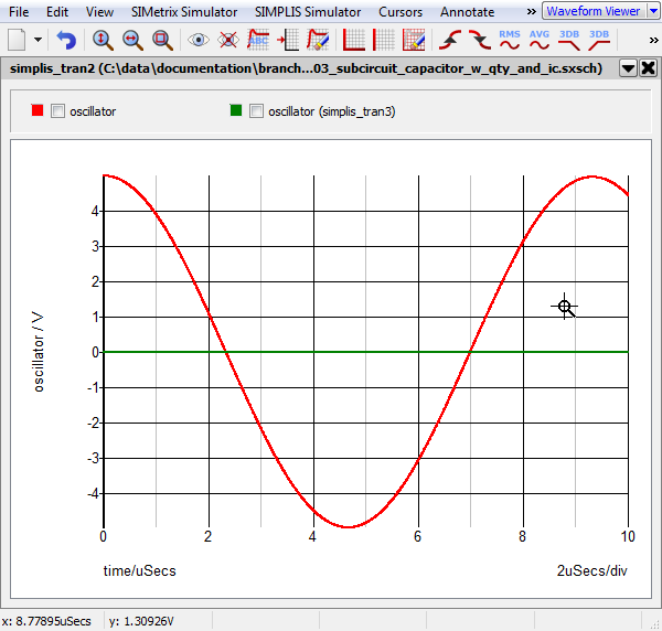
Waveforms
The waveforms show below are taken from two simulation runs. In the first run, the initial condition of the capacitor C1 was set to 5V and the USEIC parameter is true. This run (red curve) produces a sine wave oscillation with the initial voltage of 5V. For the second simulation (green curve), the USEIC parameter is false and the oscillator does not oscillate, and the initial condition of the capacitor is an open circuit and the inductor initial condition is 0V.