Initial Conditions
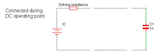
Initial conditions may be applied to capacitors and inductors and may also be applied to a single node using the .IC statement. Initial conditions force a voltage or current to be applied during the DC operating point analysis. Here we describe the various methods to apply an initial condition.
In this topic:
Node Initial Condition
 The above shows a driving resistance of 1???MATH???\Omega???MATH???. This is the default value but can be changed using the ICRES option:
.OPTIONS ICRES=1m
The above sets the resistance to 1m???MATH???\Omega???MATH???.
Note that an initial condition may also be applied to a node or across a pair of nodes using a capacitor with a value of zero. See next section.
Capacitor Initial Condition
An initial condition may be defined for a capacitor using the IC parameter. The following
diagram shows how this is configured:

.OPTIONS INITCONDMODE=0|1|2
Cxxxx n1 n2 capacitance IC=init_condition BRANCH=0|1
The different configurations have come about because of a need for compatibility with other simulators, namely SIMPLIS, Berkeley SPICE and PSpice.
| IC | BRANCH | INITCONDMODE | Configuration |
| NO | 0 | X | No initial condition applied |
| NO | 1 | X | Initial condition=0V, driving resistance=0???MATH???\Omega???MATH??? |
| YES | 0 | 0 | Berkeley SPICE compatible. Initial condition=IC only if UIC specified on .TRAN statement |
| YES | 0 | 1 | SIMPLIS compatible. Initial condition=IC, driving resistance=0???MATH???\Omega???MATH??? |
| YES | 0 | 2 | PSpice compatible. Initial condition=IC, driving resistance=ICRES (default=1???MATH???\Omega???MATH???) |
| YES | 1 | X | SIMPLIS compatible. Initial condition=IC, driving resistance=0???MATH???\Omega???MATH??? |
Note that for full PSpice compatibility, the ICRES option should be set to 1m. Alternatively the option setting PSPICECOMPATIBILITY=1 or PSPICECOMPATIBILITY=2 may be set which sets ICRES to 1m and INITCONDMODE to 2.
Inductor Initial Condition
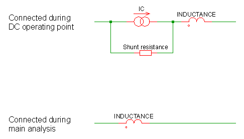
An initial condition may be defined for a inductor using the IC parameter. The following
diagram shows how this is configured:

.OPTIONS INITCONDMODE=0|1|2
Lxxxx n1 n2 inductance IC=init_condition BRANCH=0|1
The different configurations have come about because of a need for compatibility with other simulators, namely SIMPLIS, Berkeley SPICE and PSpice.
| IC | BRANCH | INITCONDMODE | Configuration |
| NO | 1 | X | No initial condition applied |
| NO | 0 | X | Initial condition=0A, shunt resistance=???MATH???\infty???MATH??? |
| YES | 1 | 0 | Berkeley SPICE compatible. Initial condition=IC only if UIC specified on .TRAN statement |
| YES | 1 | 1 | SIMPLIS compatible. Initial condition=IC, shunt resistance=???MATH???\infty???MATH??? |
| YES | 1 | 2 | PSpice compatible. Initial condition=IC, shunt resistance=1e9 ???MATH???\Omega???MATH??? |
| YES | 0 | X | SIMPLIS compatible. Initial condition=IC, shunt resistance=???MATH???\infty???MATH??? |
| ◄ Customising Device Configuration | Overview ▶ |