Graphical Symbol Editor
In this topic:
Notes
The graphical symbol editor shares much in its operation and layout with the schematic editor. For this reason, it is recommended that, before learning how to use the symbol editor, you become competent in the operation of the schematic editor. In some parts of the following sections the explanations assume that you are already familiar with the schematic editor.
Symbol Editor Window
The following diagram shows the main elements of the symbol editor
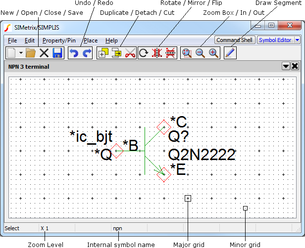
The Elements of a Symbol
Schematic symbols are composed of a combination of the following elements. All symbols that represent an electrical device would comprise all of these elements. Symbols used purely for annotation would not need pins and may not need one or other of the remaining elements either. The schematic caption, for example, is a symbol that consists purely of properties.
- Segments. These make up the visible body of the symbol. They include straight line segments and arc segments.
- Pins. These define electrical connections to the device.
- Properties. Properties have a name and a value and are used to define the behaviour of the device represented by the symbol. They can also be used for annotation, for example, a label or a caption.
Creating a New Symbol
Select the menu . This will open a symbol editor window as shown above. Now create the elements of the symbol as described above. Details are provided in the following sections.
Editing an Existing Symbol
Select the menu and select the symbol you wish to edit. See Symbol Library Manager for details.
If you wish to edit a symbol that is placed on an open schematic, select the symbol on the schematic then choose popup menu Edit Symbol....
Drawing Straight Line Segments
Drawing straight line segments in the symbol editor is very similar to drawing wires in the schematic editor. You can do one of the following:
- Select Draw Segment Mode by clicking the Draw segment tool button. You can now draw segments using the left and right mouse buttons. Press the button again to revert to normal mode.
- If you have a three button mouse, the middle button will start a new segment. The left button will complete a segment and terminate the operation, while the right button will terminate without completing the current segment.
- Enter Draw Segment Mode temporarily by pressing F3.
- Double click the left button to start a new segment.
Drawing Arcs, Circles and Ellipses
The basic method of drawing each of the curved elements is the same for each case. Before drawing starts, you must define the start-finish angle and, for ellipses, the ratio of height to width. The drawing operation itself defines the start and finish points. For full circles and ellipses the start and finish points are on opposite sides.
Dedicated menus are supplied for starting a full circle, half circle and quarter circle. For everything else use .
When you have initiated the operation, the cursor will change to a shape showing a pencil with a small circle. You can now draw the curved segment by dragging the mouse with the left key. When you release the mouse button the operation will be complete and the mouse mode will revert to normal select mode.
It is easier to demonstrate than explain. You may wish to experiment with arc/circle/ellipse drawing to gain a feel of how the system operates.
You will note that full circles are displayed with a small filled square on opposite sides. These are the select points. You can pick either one and drag it to resize the circle.
Placing and Defining Pins
Placing a Single Pin
To place a single pin, select . Place this on the sheet by left clicking the mouse at your desired location. Note that pins always snap to major grid points. (See diagram in section Symbol Editor Window).
The first pin you place on the sheet will be called '*pin'. The * signifies that the pin name will not be visible when the symbol is placed on a schematic.
Editing Pin Attributes
To edit the attributes of the pin, (e.g. to change its name or visibility) select either the pin or its label with the left mouse key then press F7 or select popup menu Edit Property/Pin/Arc...
. This will display the following dialog:
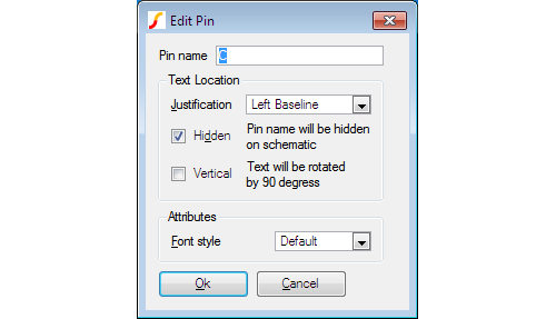
Pin name
Must be unique within the symbol and may not contain spaces.
If the symbol is to be used as a hierarchical block, the pin name must match the names of the module ports on the schematic which it represents.
If the symbol is to be used for an existing sub-circuit from, for example, a model library, the pin names are not important and you can choose any suitable name. The pin names do not need to match the node names in the sub-circuit definition.
Text Location
| Justification | If the pin name is visible this specifies its alignment. |
| Hidden | Check this box if you do not wish the pin name to be visible on the schematic. |
| Vertical | The pin's label will be displayed vertically if this is checked. |
Attributes
| Font style | Select font style to use for a visible pin name. There is a choice of 8 styles. Schematic fonts are explained in Fonts. |
Placing Multiple Pins
To place more than one pin select menu . You will be prompted to supply a Base pin name which will be used to compose the actual pin name. SIMetrix will append a number to this name to make the pin name unique. The first number used will be '0' unless you append the Base name with a number in which case your appended number will be used as the starting point. For example, if you supplied a Base name of DATA, the first pin placed will be called DATA0, the second DATA1 etc. assuming there aren't already pins of that name on the sheet. If you supplied a base name of DATA2, the first pin you place will be called DATA2, the second DATA3 etc.
Editing Multiple Pins
You can only edit the names of pins one at a time, but you can edit the attributes of a group of pins in a single operation. First select all of the pins you wish to edit. Selecting is done in the same manner as for the schematic except note that you can select the pins themselves or the pin names; either will do. Now press F7 or select popup menu Edit Property/Pin/Arc.... You can change any of the pins attributes except its name and the change will be applied to all selected pins.
Moving Pins or Pin Names
Moving any item in the symbol editor is done the same way as in the schematic. Note, however that pin names are attached to the pins. If you move a pin, its name moves with it. You can move the name on its own by making sure that only the name is selected and not the pin.
Defining Pin Order
The symbol's pin order is important if you are defining a symbol for use with a sub-circuit or primitive simulator device. If it is a sub-circuit, the symbol's pin order must match the order in which the corresponding nodes are defined in the .SUBCKT statement. If the symbol is a primitive device, then it must follow the order defined in section Summary of Simulator Devices.
If you are creating a symbol for a hierarchical block, you do not need to define the pin order. The connection between the symbol and the underlying child schematic is made by name.
To define the symbol's pin order select menu . Use the up and down buttons to reorder the pins as appropriate.
Adding XSpice Pin Attributes
Some XSPICE devices support vector connections and/or variable type connections. These are designated in the netlist with the characters '[', ']' and '%' and are explained in Simulator Reference Manual/Simulator Devices/Using XSPICE Devices. You can add these to a symbol by prefixing the appropriate pin name with the same characters as required in the netlist. E.g. to start a vector connection at a pin named IN1 enter the pin name [IN1. To close a vector connection at pin IN3 use pin name IN3].
Similarly to change a connection whose default type is 'v' (i.e. a single-ended voltage) to a differential current (type%id), prefix the first pin name with%id and a space. E.g. pin name 'VIN' would become '%id VIN'.
Examples of the use of vector connections in symbols can be found with any of the digital gate symbols.
Defining Properties
Properties define the behaviour of the symbol. For full documentation on the use of properties, see section Properties. In this section, the methods of adding and editing properties in the symbol editor are described.
Adding a Single Property
To add a property to a symbol, select . You will see the following dialog box:
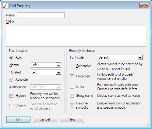
This box allows you to define the name, value and attributes of the property. Note that if the property is not protected, the value and attributes can be changed after the symbol has been placed on a schematic using the schematic popup Edit Properties....
Name
Name of property. This would usually be one of the special properties documented in Properties. You can, however, add any property name you wish to display as text or to provide a special function that you define in a custom script. The only restriction is that the name must not contain spaces.
Value
The property's value. (Don't confuse this with the Value property). You can insert a new line by pressing the ENTER key. But be careful that if you press the ENTER key accidentally intending to close the dialog that you must delete the erroneously entered new line.
Text location
Define the position of the property's value text on the schematic.
| Auto/Absolute | When auto is selected, the property's value text is positioned automatically outside the symbol's border according to the options specified in Normal and Rotated. When absolute is selected, the property is placed at a fixed position relative to the symbol body. You can define the location interactively with the mouse. When auto is selected, the text is always horizontal, when absolute is selected, the text is vertical when the symbol is at a 90 degree rotation. |
| Normal | When auto is selected, this specifies which side of the symbol the text is located when the symbol is in normal orientation. |
| Rotated | When auto is selected, this specifies which side of the symbol the text is located when the symbol is rotated 90 degrees. |
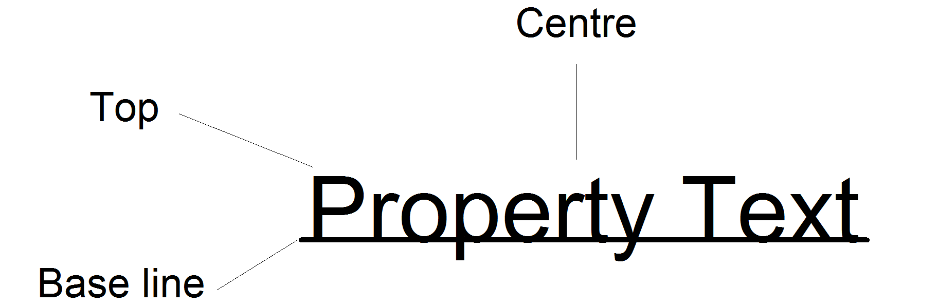
| Justification | Defines the reference point on the text when absolute is specified. See diagram below for meaning of options. The reference point is always at a fixed location with respect to the symbol body. The position of the remainder of the text may vary with zoom level or font size. |
| Hidden | The property's value text will not be displayed in the schematic. |
| Vertical | If checked, the property will be displayed vertically. This option is only available if absolute location is selected. |
Property Attributes
| Font style | Select one of eight font styles. The actual font definition is defined by the Font dialog box. See Fonts for details. |
| Selectable | If checked, the instance of the symbol owning the property can be selected by clicking in the property text. It is recommended that this option is off unless the symbol has no body e.g. a pure text item. |
| Protected | If checked, it will not be possible to edit or delete the property on a schematic instance of the symbol. |
| Linear | When this is not checked, the size of the font is adjusted for best readability and does not necessarily scale exactly with the zoom magnification. When the box is checked, the font size follows the magnification in a linear fashion. |
| Show | Name If selected the name of the property as well as its value will be displayed. |
| Resolve symbolic | The value may contain expressions enclosed by '{' and '}', keywords enclosed by '<' and '>' and property names enclosed by '%'. These items will each be substituted with their resolved value to obtain the property text that is actually displayed. Expressions may contain the usual arithmetic operators and may also use functions as defined in Script Reference Manual/Function Reference. Property names enclosed with '%' are substituted with that property's value. Keywords may be <date>, <time>, <version>, <if>, <ifd> and <t>. <date>, <time> resolve to date and time in local format and <version> resolves to an integer value which is incremented each time a schematic is saved. The keywords <if>, <ifd> and <t> behave in the same manner as the TEMPLATE property keywords of the same name. See Template Property for details. Note that, like template properties, the resolution is performed in two passes with the property values being substituted first. |
Adding Standard Properties
Select menu . This prompts you for values for the ref, value and model properties. These properties are usually specified for all symbols, with the exception of hierarchical blocks which do not require a Value property. If you are using the SIMetrix/SIMPLIS product, you will also be prompted to supply a value for the SIMULATOR property.
The following table describes the four standard properties.
| Property name | Function | ||||||
| Ref property | This is the part reference e.g. U1, R3 etc. This would conventionally be a letter or letters followed by a question mark ('?'). When you place the part on the schematic, the question mark will be replaced automatically by a number that makes the reference unique. If you don't specify a Model property (see below), the first letter of the reference is important as it defines the type of device. This is explained in more detail below. | ||||||
| Value property | This is the device's value or model name including any additional parameters. For a resistor this might be 12k for an op-amp, LM324, or for a bipolar transistor, Q2N2222. The Value property must be present on a symbol at the definition stage but its initial value is not important as it would usually be changed after the symbol is placed on a schematic. | ||||||
| Model property | This property usually has a value that is a single letter that specifies the type of device. For sub-circuits and hierarchical blocks this letter must be 'X'. For other types of device refer to the table in Summary of Simulator Devices. If this property is not present, the first letter of the Ref property will be used to identify the device. For information only: The value of this property and a '$' symbol are prefixed to the ref property to obtain the first word of the device line in the netlist hence complying with SPICE syntax. (This won't be done if the first letter of the Ref property is already the same as the value of the Model property as this would be unnecessary.) | ||||||
| Simulator property |
This is only required for the SIMetrix/SIMPLIS product. It declares which simulator the symbol is compatible with. This is only for the purpose of advising the user if a part may not work with a particular simulator. It does not affect the functionality of that part for any simulator.
This property can have one of three values:
|
Editing a Property
To edit a property, select it then press F7 or select popup menu Edit Property/Pin/Arc.... This will open a dialog box very similar to the one described above but without the option to enter a property name. Make the appropriate changes then Click Ok.
Saving Symbols
To save the current symbol, select menu . The following dialog will be displayed:
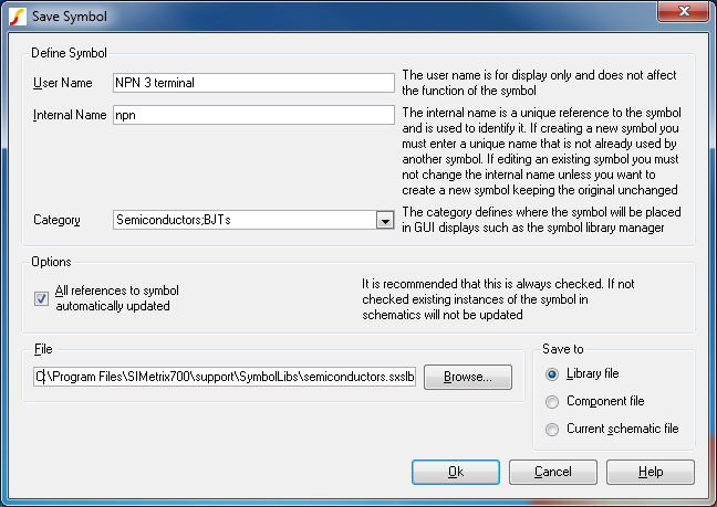
Define Symbol - User Name
Enter the name as you wish it to be displayed in the dialog box opened with the schematic menu .
Define Symbol - Internal Name
For a new symbol, an internal name will automatically be entered when you type the User Name. In most cases you can leave it at that. However, the internal name must be unique across the whole model library so there may be situations where you will need to change it. If you are unsure whether the name used is unique, prefix it with something that is very unlikely to be used anywhere such as your initials. The resulting name does not need to be meaningful to anyone else; it is an identifying code not a descriptive name.
Define Symbol - Category
Enter a category to determine how the symbol will be listed in the dialog box opened with the schematic menu Place | From Symbol Library.... Sub-categories are separated using a semi-colon. Note that you can easily move symbols to different categories using the symbol library manager . So if you are unsure at this stage what category to use, you can place it in a temporary category and move it later.
Define Symbol - All references to symbol automatically updated
If this is checked, any changes you make to a symbol will automatically be applied to any instance of it in existing schematics whether they are open or not.
If it is not checked, instances of the symbol will not be updated until the Update Symbols menu is selected in the schematic. Copies of all symbols used by a schematic are stored locally within the schematic and that local version will only be updated if this box is checked.
See How Symbols are Stored for further details.
Save to - Library File
Saves the symbol to the library file specified in the File box. This would usually have a .SXSLB extension.
Save to - Component File
Saves the symbol as a component to the file specified in the File box. This would usually have the extension .SXCMP. Component files are used for hierarchical schematics and contain a schematic and a symbol representing it in the same file. When you save a symbol to a component file, only the symbol portion of it will be over-written. If it contains an embedded schematic, that schematic will remain unchanged. See Hierarchical Schematic Entry .
Save to - Current Schematic Only
The symbol will be saved to the currently selected schematic only and will not be available to other schematics.
File
Library or component file name - see above. Press Browse to select a new file.
| ◄ Creating Schematic Symbols - Overview | Creating a Symbol from a Script ▶ |