Analog-Digital Converter
In this topic:
Netlist entry
Axxxx analog_in clock_in [ data_out_0 data_out_1 .. data_out_n ]
+ data_valid model_name
Connection details
| Name | Description | Flow | Type | Allowed types | Vector bounds |
| analog_in | Analog input | in | v | v, vd, i, id | n/a |
| clock_in | Clock input | in | d | d | n/a |
| data_out | Data output | out | d, vector | d | 1 - 32 |
| data_valid | Data valid output | out | d | d | n/a |
Model format
.MODEL model_name ad_converter parameters
Model parameters
| Name | Description | Type | Default | Limits |
| input_offset | Offset voltage | real | 0 | none |
| input_range | Input full scale signal range | real | 1 | none |
| twos_complement | Use 2's complement output. (default - offset binary) | boolean | FALSE | none |
| convert_time | Total conversion time | real | 1 ???MATH???\mu???MATH??? S | ???MATH???0 - \infty???MATH??? |
| min_clock | Minimum clock period | real | 500n | ???MATH???0 - \infty???MATH??? |
| data_valid_delay | Data valid inactive time | real | 100n | ???MATH???0 - \infty???MATH??? |
| in_family | Input logic family | string | UNIV | none |
| out_family | Output logic family | string | UNIV | none |
| family | Logic family | string | UNIV | none |
| input_load | Input load | real | 1pF | ???MATH???0 - \infty???MATH??? |
| out_res | Digital output resistance | real | 100 | ???MATH???0 - \infty???MATH??? |
| out_res_pos | Digital output res. pos. slope | real | out_res | ???MATH???0 - \infty???MATH??? |
| out_res_neg | Digital output res. neg. slope | real | out_res | ???MATH???0 - \infty???MATH??? |
| min_sink | Minimum sink current | real | -0.001 | none |
| max_source | Maximum source current | real | 0.001 | none |
| sink_current | Input sink current | real | 0 | none |
| source_current | Input source current | real | 0 | none |
Device Operation
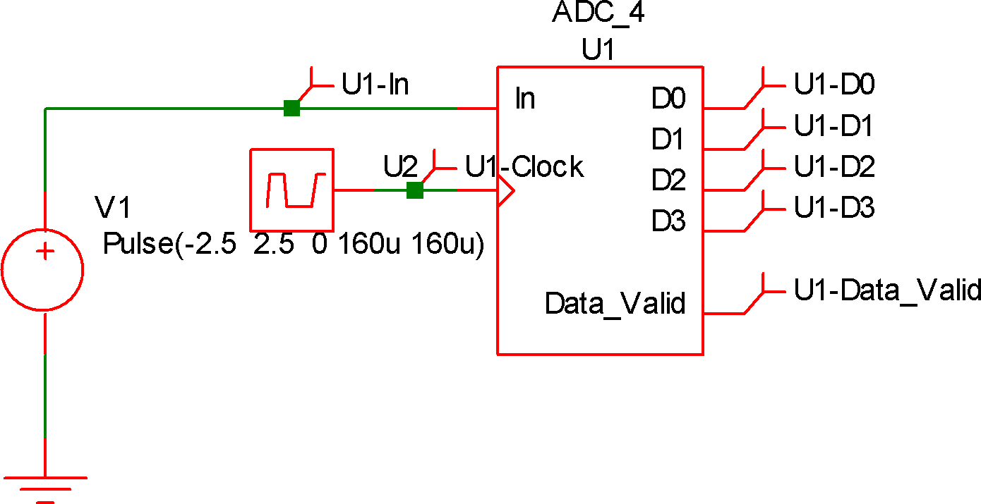
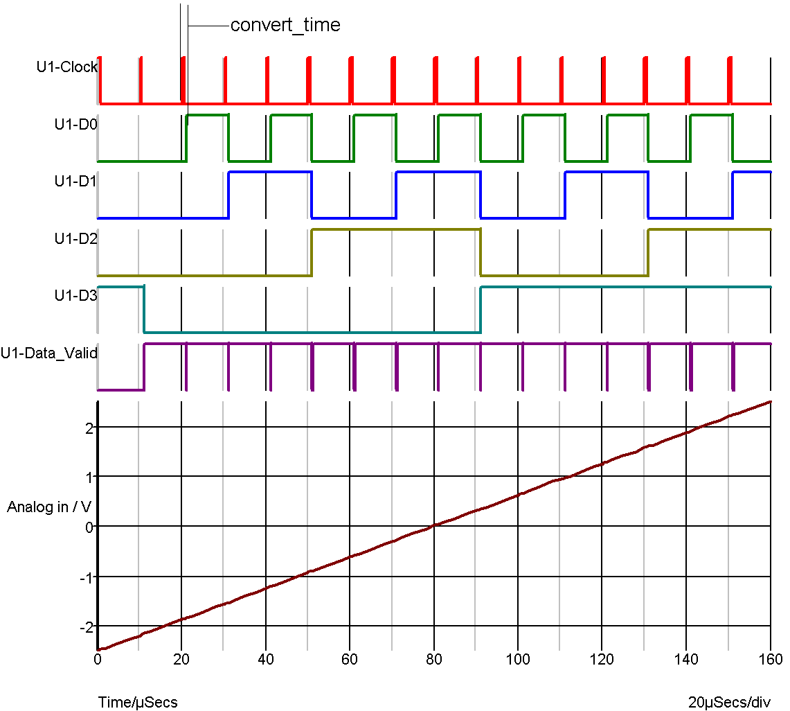
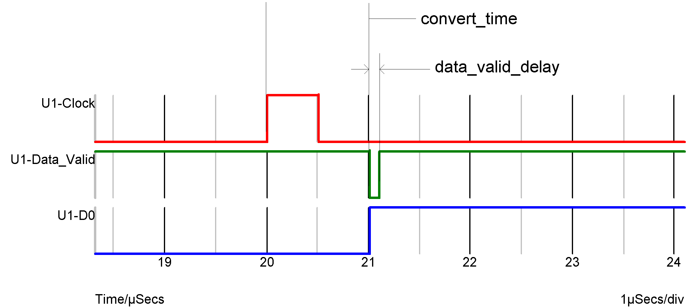
This is a 1-32 bit analog to digital converter. The operation of this device is illustrated by the following diagrams:


Conversion timings.
The ADC starts the conversion at the rising edge of the clock. The analog input signal is also sampled at this point. The output data changes in response to this, CONVERT_TIME seconds later. At the same time the data_valid output goes low (inactive) then high again after a delay equal to DATA_VALID_DELAY. It is possible to start a new conversion before the previous conversion is complete provided it is started later than MIN_CLOCK seconds after the previous conversion was started. MIN_CLOCK must always be less than CONVERT_TIME. If the MIN_CLOCK specification is violated, the conversion will not start.
| ◄ Exclusive OR Gate | Analog-Digital Interface Bridge ▶ |