Schematic Symbol Script Definition
It is possible to define a schematic symbol using a script. This method is used in some of the internal scripts to create dynamic symbols. For example the transformer devices allow the user to define the number of both primary and secondary windings. The symbols for these are not stored in the symbol library but generated programmatically using the commands described in this section.
Symbol scripts can also be useful to edit symbols using a text editor. Some operations can be more rapidly performed by editing a text definition than by using a graphical editor. To support this method, SIMetrix includes the MakeSymbolScript command that writes a script definition of a symbol in ASCII form.
The following sections describe how to define a symbol using a script.
In this topic:
Defining New Symbol
- Enter the text definition as described in Symbol Definition Format into a text file (using NOTEPAD for example)
- Load the new definition by simply typing the name of the file at the command line
- Test that your new symbol is as you expect. Use the menu Place|From Symbol Library to place your symbol on a schematic
To update the symbol on a schematic from the global library use the popup menu Update Symbols.
Symbol Definition Format
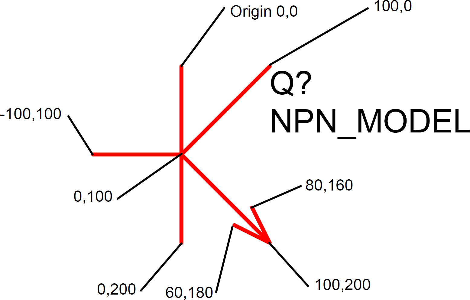
* NPN BJT
CreateSym npn "NPN bipolar" analog
AddSeg 0 0 0 200
AddSeg 0 100 100 0
AddSeg 0 100 100 200
AddSeg 100 200 80 160
AddSeg 100 200 60 180
AddSeg 0 100 -100 100
AddPin C 1 100 0
AddPin B 2 -100 100
AddPin E 3 100 200
AddProp ref Q? 26
AddProp value NPN_MODEL 26
AddProp model Q 64
EndSym
Let's go through it line by line. The first line:
* NPN BJTis a comment. Any text may placed after a '*' as the first character will be ignored. The next line:
CreateSym npn "NPN bipolar" analogbegins the symbol definition. The first argument - npn - is the symbol name. This must be unique and cannot contain spaces. It is used to place the symbol on a schematic. The second argument is the description and is optional. This is what will appear in the choose symbol dialog box opened by the schematic popup Place|From Symbol Library... menu item. If no description is given the symbol's name will appear in this dialog box. The final parameter is the catalog name. This is used to categorise symbols. Although the parameter is optional, it is strongly recommend that it is included.
AddSeg 0 0 0 200
AddSeg 0 100 100 0
AddSeg 0 100 100 200
AddSeg 100 200 80 160
AddSeg 100 200 60 180
AddSeg 0 100 -100 100
describe the symbol's six straight line segments. The four numbers on each line are the x and y co-ordinates of the start and end of each segment. 100 units represents one grid square (at X1 mag) on the schematic. The diagram shows the co-ordinates of each segment end.
AddPin C 1 100 0
AddPin B 2 -100 100
AddPin E 3 100 200
describe the location and attributes of the symbol's three pins. The first parameter on each AddPin command is the pin's name. This must be the same as the pin name used by the simulator for that type of device. If the name is different it will not be possible to cross-probe currents for that type of device. See User's Manual/Further Information/Summary of Simulator Devices for details of pin names for devices supported by the simulator. If the device is a subcircuit then any pinname may be used. The second parameter is the pin's number. This affects the order in which the pin's connected nets appear in the netlist. This must comply with the netlist format. Again refer to "Summary of Simulator Devices" for full details of each device. The last two parameters specify the co-ordinates of the pins on the schematic. They must be a multiple of 100. If they are not it will not be possible to connect to them as wire ends always snap to a grid point. See AddPin for more details.
AddProp ref Q? 26
AddProp value NPN_MODEL 26
AddProp model Q 64
are the symbol's properties. A symbol's component reference, value (or model name) and the type of device are all specified by properties. The first line above attaches a "ref" property (aka component reference) and gives it an initial value of Q?. The final parameter '26' specifies how it should be displayed on the schematic. The model property in the third line specifies the type of device (e.g. resistor, capacitor, BJT etc.) and is always a single letter. It is not compulsory. If it is omitted the first letter of the ref property is used instead. See "Summary of Simulator Devices" for full list of devices supported by the simulator and their required model properties. Full details on properties are given in the User's manual. For more information, see AddProp command.
EndSymterminates the model definition. The symbol will not be recognised until this is executed.
How Symbols are Stored
Symbol definitions are first stored in a .sxslb file which resides in the SymbolLibs directory. These files are managed by the symbol library manager. When a symbol is placed on a schematic, a copy of that symbol definition is stored in the schematic and from then on the schematic will use that copy of it. This means that if you change a symbol definition for a schematic that is saved, when you open that schematic, it may still be using the old definition as it is saved with the schematic. Whether or not the symbol is updated automatically depends on how it was saved. If /flags 1 was included with the CreateSym command, then it will be automatically updated.
If you wish to force the schematic to use the new symbol, select the symbol or symbols then select the popup menu Update Symbols. Note that all instances of the symbol will be updated. It is not possible to have two versions of a symbol on the same schematic.
| ◄ Automating Simulations | Data Import and Export ▶ |