SystemDesigner Buses
SystemDesigneruses a unique bus system to encode and transfer SystemDesignerspecific data from one SystemDesigner component to another. Although these buses have the same graphical look as other buses on a schematic, they need to be treated differently for probing and connecting to other devices. You first need to determine if the bus is a SystemDesignerbus.
As a rule, a bus is a SystemDesignerbus if one or both of the following are true:
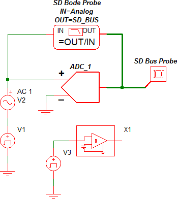
- A bus connects the output of one
SystemDesignercomponent to the input of another SystemDesignercomponent. For example, this condition exists in the tutorial
example at the interconnection between the output of the ADC and the two
probes as illustrated below.
- The other condition that determines a SystemDesigner bus is if the bus is connected to the
output
of a SystemDesignercomponent that drives another SystemDesigner component.
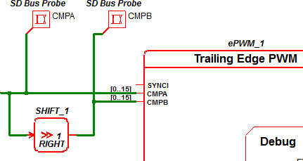
For example in the global start of conversion ( SOC ) example, a SystemDesigner component drives the input to an ePWM as shown below:
- The bus connected between the right-shift output and the ePWM-CMPA input pin is a SystemDesignerbus.
- The other bus in the this schematic is also a SystemDesigner bus connected to the output of a SystemDesigner adder block.
A bus is not a SystemDesignerbus if one of the following condition exists:
- The
output
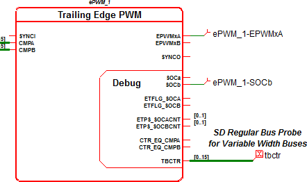
bus pin on a device has the [0..n] label where n is a positive
integer, such as the debug pins on the ePWM symbols, shown below from the global start of conversion ( SOC ) example. In this schematic, the
tbctr probe is on a regular bus, not on a SystemDesigner bus.
Compatibility between regular and SystemDesigner buses.
The above examples show that SystemDesignerbuses can be used to drive regular bus inputs on other SystemDesigner components. During an integer-sampled data simulation, the SystemDesigner buses are 32-bit buses in a two's complement format. As such, the output is compatible with an unsigned bus as long as the value of the bus does not exceed 2^31. Currently, only the SystemDesigner ePWM module has non-SystemDesigner buses.
On the other hand, regular buses cannot be used to drive SystemDesigner buses because regular buses do not properly format the SystemDesigner data for the double-precision floating-point simulations.
Probing
Because of the special nature of the SystemDesigner buses, specific probes have been developed to generate curves from these buses. These probes may be placed from the Parts Selector section: SystemDesigner Functions (max 32 bit) | Probes:
SystemDesigner - Bus Probe (SD Buses)
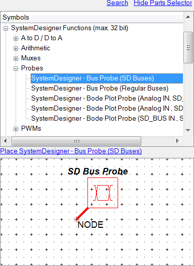
The SystemDesigner - Bus Probe (SD Buses) is the probe used in the SystemDesigner tutorial example and is the probe that you will use most often in SystemDesigner . Use this probe for any buses which are SystemDesignerbuses. This probe does not produce curves for non-SystemDesigner buses, nor does it produce curves for any non-SystemDesigner simulations.
SystemDesigner - Bus Probe (Regular Buses)
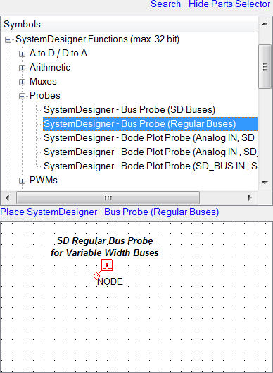
The SystemDesigner - Bus Probe (Regular Buses) should be used on all non-SystemDesigner buses in any SystemDesignerschematic. The buses include any buses which are connected to the output of a regular SIMPLIS digital component.
The other three probes probe the AC response between two nodes. These probes produce waveforms only for an AC simulation, which means that they are inactive for all integer-sampled data simulations. To cover all the combinations of buses, three probes are included in the Parts Selector:
- SystemDesigner - Bode Plot Probe (Analog IN, SD_BUS OUT)
- SystemDesigner - Bode Plot Probe (SD_BUS IN, Analog OUT)
- SystemDesigner - Bode Plot Probe (SD_BUS IN, SD_BUS OUT)
These three Bode plot probes have edit dialogs identical to the conventional Bode plot probe used in SIMetrix/SIMPLIS.