SIMPLIS - Time Domain, All the Time
SIMPLIS operates just like your circuit in the laboratory - in the time domain.
- Your power electronic switching system in the lab has no concept of a DC operating point or an AC model.
- The power switches turn ON and then OFF as determined by a pulse-width modulator control that senses the output and tries to regulate the circuit performance accordingly.
- If the circuit is not switching, it is not working correctly.
- A PWM has no DC operating point.
- An averaged AC model is a theoretical construct, it does not exist on the lab bench.
SIMPLIS was designed to model the actual time-domain behavior of a switching power electronic system. Real circuits exist only in the time domain, not in the frequency domain. SIMPLIS models nonlinear switching time domain behavior all the time. However, as in the laboratory, time-domain switching systems in steady state may be measured in the time domain with results plotted in the frequency domain. In the laboratory, you use a network analyzer to perturb a time domain circuit and then view the frequency sweep after the time domain data is processed with a Fourier analysis. This is the manner in which frequency-domain characterizations are performed in the lab on real hardware, which always operates in the time domain although some steady-state time-domain behavior can be usefully plotted in the frequency domain. All SIMPLIS AC analyses are performed in this way, on a single time domain circuit.
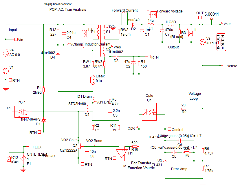
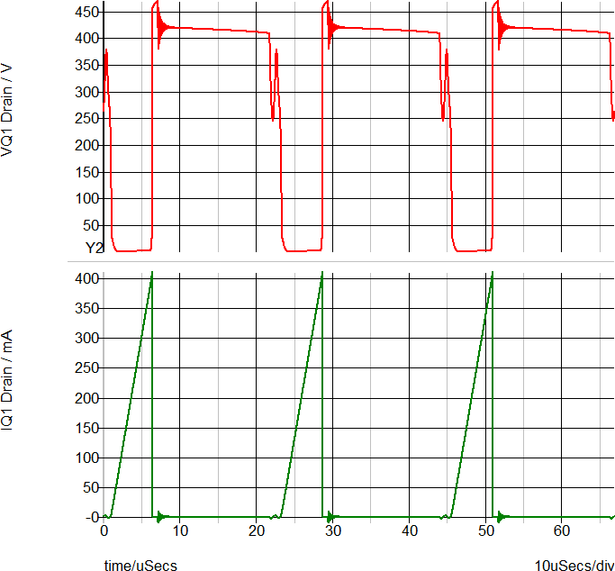
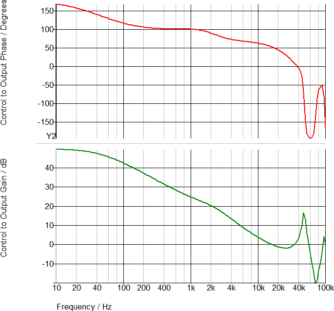
As a working example of SIMPLIS time domain simulations, the Self Oscillating converter from the What is SIMPLIS? topic is pictured below. This converter oscillates at a frequency dependent on the load current, which prevents the easy derivation of a small signal averaged model. Using the SIMPLIS POP analysis, the steady state behavior is quickly simulated, then the SIMPLIS AC analysis simulates the loop response on the same time domain model. The simulation results for this converter have been compared to hardware measurements. For information on how SIMPLIS simulations compare with real hardware measurements, see the Accuracy of PWL Models topic.
| Time Domain Waveforms | Frequency Response of Time Domain Model |
|
|
|
|