Trailing Edge PWM
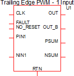
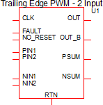
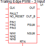
The Trailing Edge PWM block is a general purpose PWM block with leading-edge blanking, a fault signal, and a toggle Flip-Flop option. This block does NOT contain an oscillator; instead, you can use your own oscillator or one of the built-in oscillator models:
- Voltage-Controlled Oscillator w/ Programmable Duty Cycle
- Voltage-Controlled Oscillator w/ 50% Duty Cycle
The Trailing Edge PWM block sums all positive inputs ( PIN1, PIN2, ...) and outputs that sum on the PSUM pin. Similarly, all negative inputs are summed and output on the NSUM pin. The output signal, OUT is high when PSUM is greater than NSUM, except during the interval when the clock signal is high in which case OUT is forced low.
The FAULT input drives the OUT pin to the low state, independent of the other inputs. Leading-edge blanking is provided using the NO_RESET input. When NO_RESET is high, the OUT pin cannot be driven low via the PWM comparator. The CLK and FAULT pins can drive the OUT low during the time period when the NO_RESET pin is high.
Although three inputs are provided, not all inputs need to be connected in the circuit. Unused input pins are pulled to the RTN voltage with resistor pull-downs. See the Examples sections for a schematic example.
In this topic:
| Model Name: | Basic Trailing Edge PWM Block | ||||
| Simulator: | This device is compatible with the SIMPLIS simulator. | ||||
| Parts Selector Menu Location: |
|
||||
| Symbol Library: | simplis_analog_functions.sxslb | ||||
| Model File: | simplis_analog_functions.lb | ||||
| Subcircuit Name: |
|
||||
| Symbols: |
|
||||
| Multiple Selections: | Multiple devices can be selected and edited simultaneously. | ||||
Previous Version Compatibility
The 1 and 2 input symbols and electrical models were introduced with version 8.0. These models will not simulate in versions prior version 8.0.
The three input symbol will simulate in versions prior to version 8.0, and the dialog function will work in version 7.20.
For a Trailing Edge PWM compatible with versions prior to version 7.20, see the parts selector entry:
The obsolete PWM symbol uses the same electrical model (3-input) but with a different symbol and editing dialog.
Symbol Migration
Symbols placed on schematics in previous versions of SIMetrix/SIMPLIS can be automatically migrated to use the new symbols. The schematic tools menu will invoke a routine which migrates the existing symbols to the new symbols. As this action makes substantial changes to the schematic, it is recommended that you save a backup copy of the schematic first.
I/O Table
The following table describes the pins on the Trailing Edge PWM symbol.
| Pin_Name | I/O | Function | Description |
| CLK | I | Clock signal digital input | Output is low for duration of interval where the clock signal is high. |
| PSUM | O | Analog output signal | Numerically equal to the sum of PIN1+PIN2+PIN3. This signal is also the positive input of the PWM comparator in this circuit. |
| NSUM | O | Analog output signal | Numerically equal to the sum of NIN1+NIN2+NIN3. This signal is also the negative input to the PWM comparator in this circuit. |
| PIN1 PIN2 PIN3 |
I | Analog input signals | These three signals are summed to create PSUM. If a given input is not connected, its input value is 0. |
| NIN1 NIN2 NIN3 |
I | Analog input signals | These three signals are summed to create NSUM. If a given input is not connected, its input value is 0. |
| OUT | O | Digital PWM Output signal |
OUT is low whenever the CLK or FAULT inputs are high.
Normally, OUT goes high on the trailing edge of the CLK signal.
|
| OUT_BAR | O | Digital PWM Output signal | OUT_BAR is the logical inverse of OUT. |
| FAULT | I | Digital input signal | Whenever the FAULT signal is high, the OUT signal is forced low. |
| NO_RESET | I | Digital input signal | Leading Edge Blanking Input. Once LEB (leading-edge blanking) is high, the OUT signal cannot be set low while NO_RESET is high unless either the CLK or FAULT signal goes high. |
| RTN | Circuit return for this circuit | Ground reference for the PWM |
Editing the Trailing Edge PWM
To configure the Trailing Edge PWM, follow these steps:
- Double click the symbol on the schematic to open the editing dialog.
- Make the appropriate changes to the fields described in the table below the image.
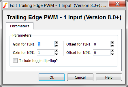
| Label | Parameter Description |
| Gain for PIN1 | Gain values for PIN1, PIN2, and PIN3; default is 1. |
| Gain for NIN1 | Gain values for NIN1, NIN2, and NIN3; default is 1. |
| Offset for PIN1 | Offset values for PIN1, PIN2, and PIN3; default is 0. |
| Offset for NIN1 | Offset values for NIN1, NIN2, and NIN3; default is 0. |
| Include toggle flip-flop? | Adds a toggle flip-flop to the PWM. See the Examples. |
Example - General PWM Operation Example
The test circuit used to generate the waveform examples in this section can be downloaded here: simplis_072_trl_edg_pwm_1.sxsch.
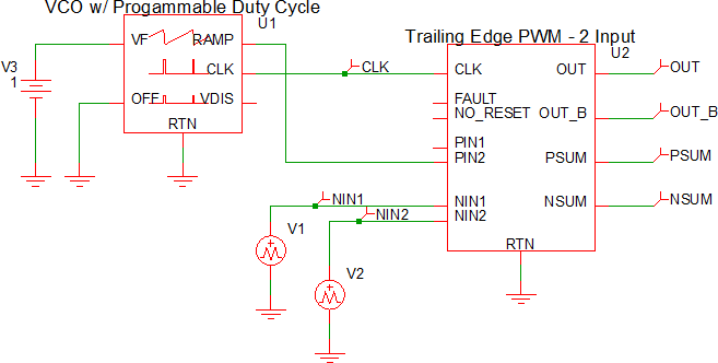
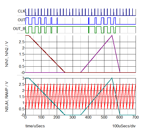
The waveform below shows the results from the schematic above.
- Since the Include toggle flip-flopis checked, OUT is triggered on every other CLK trailing edge. Since the Ramp signal is the only PIN input, PSUM = PIN2 = RAMP in the test circuit.
- NIN1 + NIN2 = NSUM.
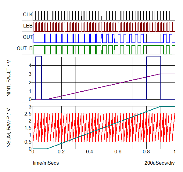
Example - Fault and Leading Edge Blanking (LEB) Operation
In the schematic below, the leading-edge blanking signal is generated from the RAMP and fed into the NO_RESET input. The FAULT signal is exercised to override all other inputs and force OUT to low. This circuit can be downloaded here:
simplis_072_trl_edg_pwm_2.sxsch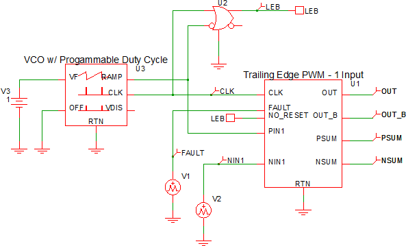
In the waveform below, OUT is always low when FAULT is high. The NO_RESET signal is used to define a minimum pulse width for OUT, which generates the leading-edge blanking. Since the Include toggle fliep-flop is checked, OUT is triggered on every other CLK trailing edge.