Transfer Function
Transfer function analysis is similar to AC analysis in that it performs a swept small signal analysis. However, whereas AC analysis calculates the response to all circuit nodes from a (usually) single input source, transfer function analysis calculates the individual responses from each source in the circuit to a single specified output node. This allows, for example, the series mode gain, common mode gain and power supply rejection of an amplifier to be measured in one analysis. The same measurements could be performed using AC analysis but several of them would need to be run. Transfer function mode also calculates output impedance or admittance and, if an input source is specified, input impedance.
In this topic:
Setting up a Transfer Function Analysis
- Select menu
- Select TF check box on the right.
- Select TF tab at the top. Enter parameters as described in the following sections.
Sweep Parameters
| Start value, Stop value | Defines sweep range stop and start values. |
| Points per decade, Number of points | Defines sweep range. The number of points of the sweep is defined per decade for a decade sweep. For a linear sweep you must enter the total number of points. |
| Define... | Sets up desired sweep mode. See Setting up a Swept Analysis. |
Transfer Function Parameters
| Voltage/Current | Specify whether the output is a node voltage or device current. |
| Output node/Output source | This is compulsory. If voltage mode is selected it is the name of the circuit node to which the gain of all circuit sources will be calculated It is the node name as it appears in the netlist. Usually the schematic's netlist generator chooses the node names but we recommend that when running a transfer function analysis that you assign a user defined name to your designated output node. To find out how to do this see Finding and Specifying Net Names. If current mode is selected it is the name of a voltage source through which the output current is measured. The simulation will calculate the gain for every circuit source to this current. |
| Reference node | Optional and only available in voltage mode. Output voltage is referred to this node. This is assumed to be ground if it is omitted. |
| Source name | Optional. Input impedance to this source will be calculated if specified. |
Monte Carlo and Multi-step Analysis
See Multi-step Analyses.
See Also
Plotting Transfer Function Analysis Results
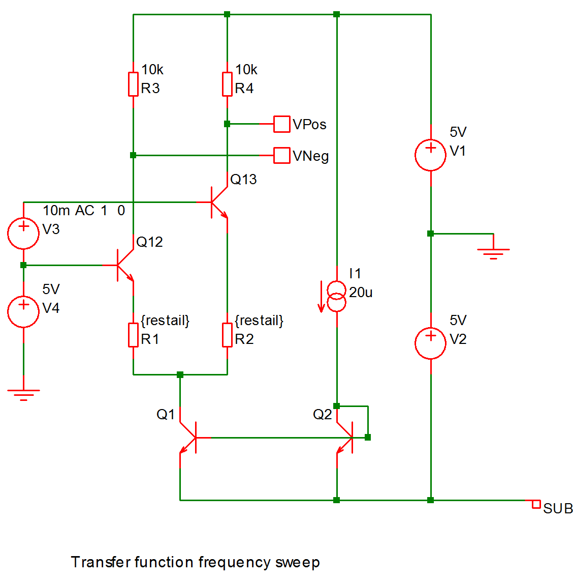
Example
Perform transfer function frequency sweep on the following circuit
 The results:
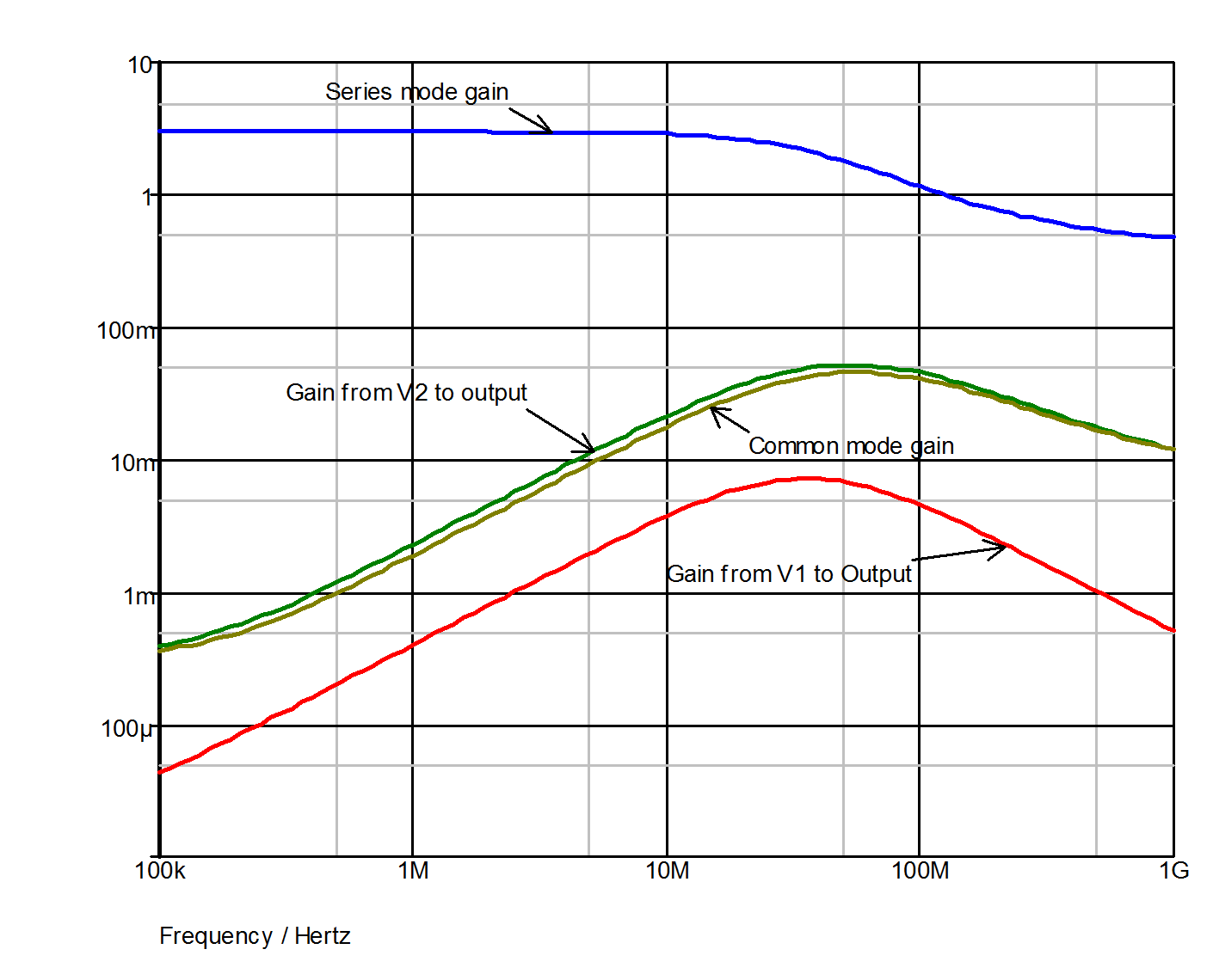
All of the above waveforms were created with a single analysis.
| ◄ Real Time Noise | Sensitivity ▶ |