6.2 Assembling the Subcircuit Load
To download the examples for Module 6, click Module_6_Examples.zip
In this topic:
What You Will Learn
- How to include or exclude schematic components from the simulation using a conditional expression on the SIMPLIS_TEMPLATE property.
- How to create a single load which can use one of the three loads from the previous topics:
Getting Started
In the three previous topics, you created constant resistance, constant current, and constant voltage load subcircuits. Each load is self-contained with parameters passed into the underlying model through the symbol, and each load has a parameter editing dialog to edit the parameters. While these loads are well designed, with a convenient parameter editing dialog, a user has to manually delete one load symbol and replace it with another when changing the load type.
In this topic, you will "merge" these three loads into a single load which will use one of the three loads based on a parameter value. You will define the LOAD_TYPE parameter to select which one of the three loads to use in the simulation. The techniques learned in this topic are applicable to a wide range of models.
To start assembling the load subcircuits,
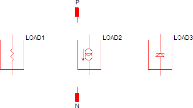
- Open the prepared schematic component: 6.2_subcircuit_load.sxcmp from the C:\Training\Module_6_Examples\Modeling Blocks directory. This schematic component has the two hierarchical ports already placed on the schematic and includes a symbol for the load.
- Using the menu, place each load created in the previous three topics. If you
skipped one of the topics, use the "answer" schematic component file (such as
6.1.3_constant_voltage_load_answer.sxcmp) in the Modeling Blocks directory.
Result: The schematic should appear similar to the following:
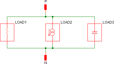
- Wire the loads so that all positive pins are connected to the P hierarchical port and all negative pins are connected to the N hierarchical port.
Result: The schematic should appear similar to the following:
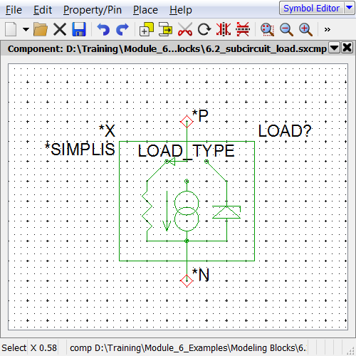
- Press S to open the symbol for the schematic component. A symbol with the
basic graphical elements is already saved in the file.Result: The symbol saved in the schematic component file opens in the Symbol Editor:
- Close the Symbol Editor and Save the schematic.
Discussion
After the getting started section, the schematic has three loads connected in parallel. Next you will modify the schematic so that only one of the three loads is used in the simulation, the load selected is determined by the parameter LOAD_TYPE.
In the three previous topics, you learned the .IF/.ENDIF constructs can be used to output error messages. In this topic you will learn the same construct can be used to exclude a schematic component from the simulation.
Exercise #1: Edit the Constant Resistance Load SIMPLIS_TEMPLATE Property
Before you get started, a note on the .IF/.ENDIF syntax when used on a template property. When a simulation is run, the SIMPLIS_TEMPLATE property is evaluated, and in that process, expressions enclosed in curly braces are evaluated, and special template keywords are resolved to text values. Because of this evaluation, the curly braces need to be doubled up when a logical test is placed on the template property. The outer-most curly braces are evaluated during the netlist process, leaving the logical test expression inside single curly braces. The syntax for using .IF/.ENDIF on the SIMPLIS_TEMPLATE property is:
.IF {{ logical_test }}
   normal_symbolic_template_property
.ENDIF
It is also important to remember that the SIMPLIS_TEMPLATE literally defines the netlist entry for a symbol. As such, you need to be very careful when editing the SIMPLIS_TEMPLATE property. In the above example, the SIMPLIS_TEMPLATE is spread out on three lines, and this is critical to the conditional expression evaluating correctly.
To edit the constant resistance load SIMPLIS_TEMPLATE property:
- Select the constant resistance load symbol.
- Press 5 to open the Edit Properties dialog.
- Double click on the SIMPLIS_TEMPLATE property.
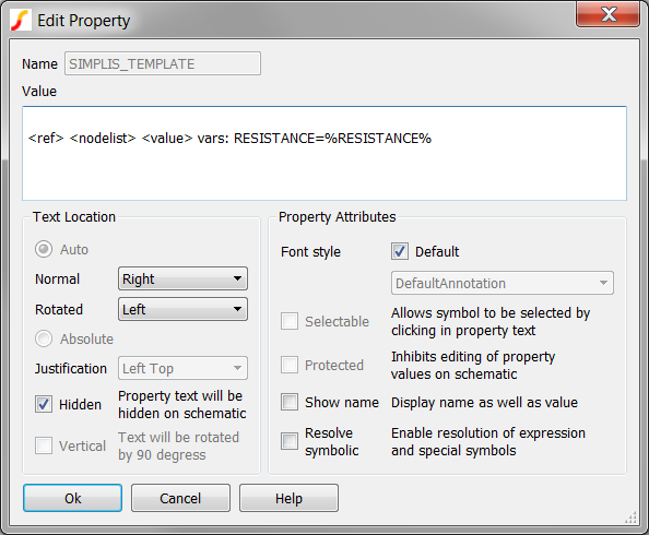
Result: The Edit Property dialog opens:
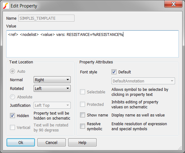
- To edit the SIMPLIS_TEMPLATE property:
- With the cursor at the beginning of the first line (this is the default
cursor position when the dialog is opened), press Enter to insert a
new line. Result: the SIMPLIS_TEMPLATE has a blank first line:
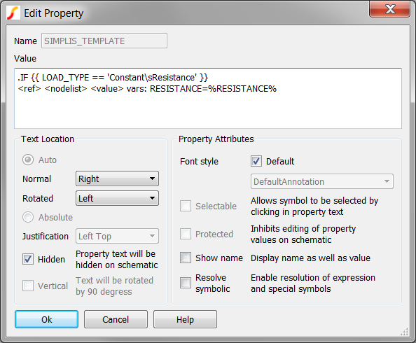
- On the first line, enter .IF {{ LOAD_TYPE == 'Constant\sResistance'
}}
Result: the SIMPLIS_TEMPLATE now appears as:
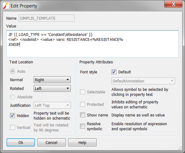
- Position the cursor at the end of the template, that is, to the right of the %RESISTANCE% text.
- Press Enter to add a new line.
- On the new line, enter: .ENDIF
Result: The final SIMPLIS_TEMPLATE property should appear as follows:
- With the cursor at the beginning of the first line (this is the default
cursor position when the dialog is opened), press Enter to insert a
new line.
- To review the SIMPLIS_TEMPLATE property value carefully, notice the following in
particular:
- The Value should have three lines.
- The first line should start with a .IF
- The first line must have two opening curly braces {{ and two closing curly braces }} around the conditional expression.
- The third line should start with a .ENDIF
- Click Ok to save the SIMPLIS_TEMPLATE property.
- Click Ok on the Edit Properties dialog.
The LOAD_TYPE parameter is a string, and will be passed into the schematic through the symbol. Consider the condition expression:
.IF {{ LOAD_TYPE == 'Constant\sResistance' }}
This conditional expression compares the string value of the LOAD_TYPE parameter to the literal string 'Constant\sResistance'. In SIMetrix/SIMPLIS, strings are enclosed in single quotes. This is an important distinction in parameter types. In all previous topics, parameters were real values, such as 1MegΩ for a resistance value. You can also define parameter values as strings; however, it is difficult to pass strings with spaces through the symbol-subcircuit interface. In this example we "escape" the space character with the character sequence \s. You will see that the dialog function automatically converts \s to a space before displaying the parameter.
The conditional expression will either return the original SIMPLIS_TEMPLATE, or an empty string, based on the string comparison. Clearly the empty string is electrically inactive and the original SIMPLIS_TEMPLATE will include the model for the constant resistance subcircuit.
Exercise #2: Edit Constant Current and Constant Voltage SIMPLIS_TEMPLATE Properties
In this exercise, you will repeat each step from exercise #1. When you get to step #4a, you will use different conditional expressions for the two loads.
- For the Constant Current Load, use
.IF {{ LOAD_TYPE == 'Constant\sCurrent' }} - For the Constant Voltage Load, use
.IF {{ LOAD_TYPE == 'Constant\sVoltage' }}
After making the changes to each SIMPLIS_TEMPLATE, double check that the syntax is correct:
- The Value should have three lines.
- The first line should start with a .IF.
- The first line must have two opening curly braces {{ and two closing curly braces }} around the conditional expression.
- The third line should start with a .ENDIF.
Exercise #3: Add .ERROR checking on the LOAD_TYPE parameter
Each subcircuit load has built-in error checking, but the new parameter LOAD_TYPE needs to be checked to ensure the string value is one of the three valid string values:
- 'Constant\sResistance'
- 'Constant\sCurrent'
- 'Constant\sVoltage'
The following conditional expression uses the logical AND operator "&&" and the logical NOT EQUAL TO inequality "!=" to check if the LOAD_TYPE parameter is not one of the three defined parameters:
.IF { LOAD_TYPE != 'Constant\sResistance' && LOAD_TYPE != 'Constant\sCurrent' && LOAD_TYPE != 'Constant\sVoltage' }
   .ERROR "The load type parameter (LOAD_TYPE={LOAD_TYPE}) for the subcircuit_load subcircuit must be one of 'Constant\sResistance', 'Constant\sCurrent', or 'Constant\sVoltage'."
.ENDIF
Copy this error message to the F11 window. and save the schematic.
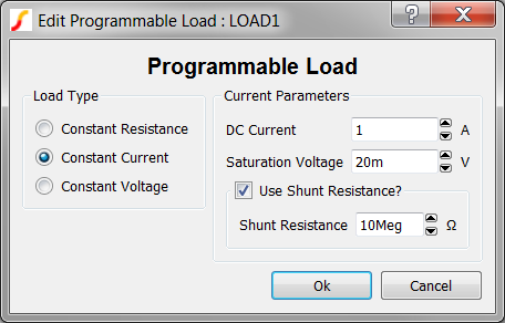
Exercise #4: Add Dialog Properties to the Symbol
Included in the Module_6_Examples.zip file is a pre-prepared dialog definition spreadsheet similar to the one used in the previous three topics. Like the spreadsheets used in 6.1.1, 6.1.2, and 6.1.3, this spreadsheet contains all script commands required to add the dialog and parameter properties to the symbol. The extracted file is located at: C:\Training\Module_6_Examples\6.2_subcircuit_load_dialog_definition_worksheet.xlsx. The dialog definition creates the following dialog for the load:
To add the symbol properties:
- Open the 6.2_subcircuit_load_dialog_definition_worksheet.xlsx excel spreadsheet.
- Copy the 16 cells: B46-B61 to the windows clipboard.
- Navigate to the SIMetrix/SIMPLIS command shell window.
- Click the mouse in the command line entry located at the top of the command shell
window:
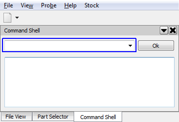
- Press Ctrl+V to paste the commands in the command line.Result: the last command is partially visible in the command line.
- Press Enter or click the Ok Button on the command line.Result: The commands are executed in SIMetrix/SIMPLIS. Each AddSymbolProperty command adds a single symbol property to the symbol. As in previous exercises, the dialog definition properties are protected. All properties are hidden from view when the symbol is placed on the parent schematic.
- Save the schematic component file.
Unlike the other models, this subcircuit load has hierarchy, and the parameters must be passed down through the hierarchy from the top level schematic component 6.2_subcircuit_load.sxcmp to the individual loads. In the next exercise you will pass the parameters from the 6.2_subcircuit_load.sxcmp schematic component to the individual loads.
Exercise #5: Pass Parameters Through Hierarchy
As discussed in topic 5.3 Passing Parameters Through Multiple Hierarchy Levels, parameters passed in through a symbol are only available at that level of hierarchy. To use these parameters in lower levels of hierarchy, such as in the three loads, you have to pass the parameters down through the hierarchy.
Start with the constant resistance load symbol:
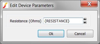
- Double click on the constant resistance symbol to edit the Resistance parameter. Enter {RESISTANCE} in the Resistance field. This is the parameter name defined on the 6.2_subcircuit_load.sxcmp symbol.
Result: The constant resistance load dialog should appear as follows:
- Click Ok to save your changes.
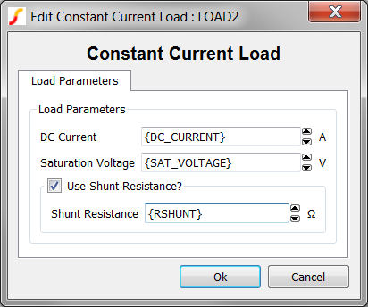
- Next double click on the constant current load symbol and then enter the
following parameters in the dialog:
- In the DC Current field, enter {DC_CURRENT}.
- In the Saturation Voltage field, enter {SAT_VOLTAGE}.
- In the Shunt Resistance field, enter {RSHUNT}. Result: The constant current load dialog should appear as follows:
- Click Ok to save your changes.
- Because the USE_RSHUNT parameter editing control is a check box, the
parameter value {USE_RSHUNT} cannot be entered on the parameter editing
dialog. Instead, follow these steps to manually enter the {USE_RSHUNT}
property value in the Edit/Add Properties... dialog:
- Select the constant current load.
- Right click and select the Edit/Add Properties... menu option.
- Double click on the USE_RSHUNT property. Result: The Edit Property dialog opens:
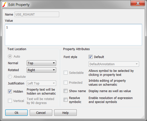
- Change the Value to {USE_RSHUNT}. Result: The Edit Property dialog should appear exactly as follows:
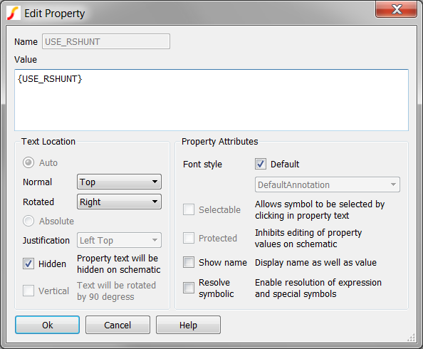
- Click Ok on the Edit Property dialog to save the changes.
- Click Ok on the Edit Properties dialog.
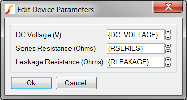
- Finally double click on the constant voltage load symbol. Enter the following parameters in the dialog.
- In the DC Voltage field, enter {DC_VOLTAGE}.
- In the Series Resistance field, enter {RSERIES}.
- In the Leakage Resistance field, enter {RLEAKAGE}.
Result: The constant voltage load dialog should appear as follows:
- Click Ok to save your changes.
- Save the 6.2_subcircuit_load.sxcmp schematic.
The model is now complete and ready for testing.
Test the Model
Now that the model and associated symbol are completed, its time to start testing. A testbench schematic for the complete subcircuit load is located in the Module_6_Examples directory. The testbench has test circuitry for each load type, so you will need to place three loads on the testbench schematic. After you place each load you should configure each of the three symbols to use one of each load type. The testbench schematic is located at: C:\Training\Module_6_Examples\6.4_test_subcircuit_load.sxsch.
This section is left as a self-study exercise. You should run the same experiments as you ran in the previous three topics:
Conclusions and Key Points to Remember
Using a conditional expression on the SIMPLIS_TEMPLATE allows you to include or exclude the entire schematic component from the simulation. This extremely powerful technique allows you to design schematics in which the schematic configuration is determined by parameter values. In this topic, you included one of three subcircuit loads, but the technique can be used for almost any application. A few examples are:
- Multi-Phase converters where the number of active phases is fixed and is determined by a parameter value.
- Multi-mode converters where the operating mode is determined by a parameter value.
- Multi-Level Modeling where the model complexity is defined by a parameter value.
The syntax of the SIMPLIS_TEMPLATE is exacting. A few rules apply:
- Expressions need to be enclosed in double curly braces. The first set is evaluated by the netlister to generate the netlist entry for the symbol. The second set is evaluated by the netlist preprocessor when the deck file is generated.
- The SIMPLIS_TEMPLATE property is taken literally - that is, any text in the value will be output to the netlist.
- New line characters are very important. The .IF/.ENDIF statements have no meaning if placed in the middle of a text string. The program requires these statements to occur at the beginning of the line.
Module Evaluation Form
At the end of the module, please fill out the Module # 6 Evaluation form.